


113413-11 Maytag Co. 11
Important
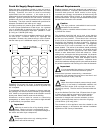
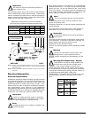
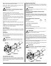
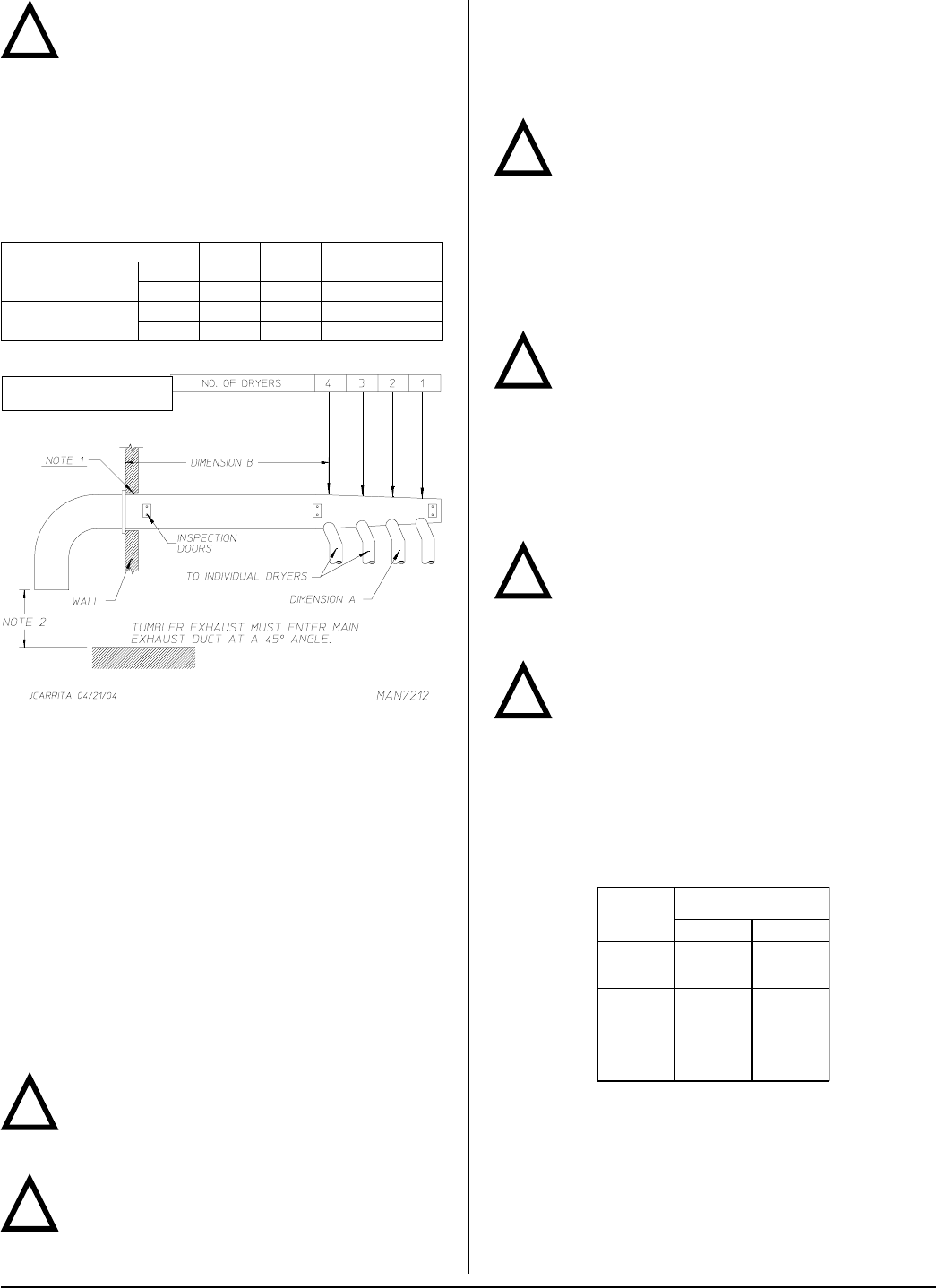
No more than 4 dryers should be connected to 1
main common duct.
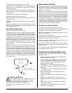
The illustration below shows the minimum cross-sectional
area for multiple dryer round or square venting. These figures
must be increased if the main duct run from the last dryer to
where it exhausts to the outdoors is longer than 12 feet (3.656
meters) or has more than 1 elbow in it.
!
NOTE 1 Opening from combustible materials must be 2-inches (5.08 cm)
larger than the duct (all the way around). The duct must be centered
within this opening.
NOTE 2 Distance should be 2 times the diameter of the duct to the nearest
obstruction.
Electrical Information _________________
Electrical Requirements
All electrical connections must be made by a properly licensed
and competent electrician. This is to ensure that the electrical
installation is adequate and conforms to local, state, and
national regulations or codes of the country of origin. In the
absence of such codes, all electrical connections, materials,
and workmanship must conform to the applicable
requirements of the National Electrical Code ANSI/NFPA NO.
70-LATEST EDITION or in Canada, the Canadian Electrical
Codes Parts 1 & 2 CSA C22.1-1990 or LATEST EDITION.
Important
Failure to comply with these codes or ordinances,
and/or the requirements stipulated in this manual
can result in personal injury or component failure.
Note
Component failure due to improper installation will
void the warranty.
A = 8-inches (20.32 cm)
B = 12 feet (3.656 meters)
NUMBER OF DRYERS 4 3 2 1
MINIMUM CROSS-
SECTIONAL AREA
SQ IN 164 120 80 54
SQ CM 1058 774.2 516.1 348.4
MINIMUM ROUND
DUCT DIAMETER
IN 14 12 10 8
CM 35.56 30.48 25.4 20.32
Each pocket should be connected to an independently
protected branch circuit. The dryer must be connected with
copper wire only. Do not use aluminum wire, which could
cause a fire hazard. The copper conductor wire/cable must
be of proper ampacity and insulation in accordance with
electric codes for making all service connections.
Note
The use of aluminum wire will void the warranty.
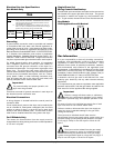
An individual ground circuit must be provided to each
pocket, do not daisy chain.
Component failure due to improper voltage application will
void the warranty.
The manufacturer reserves the right to make changes in
specifications at any time without notice or obligation.
Important
A separate protected circuit must be provided to
each pocket.
The dryer must be connected to the electric supply shown
on the data label. In the case of 208 VAC or 240 VAC, the
supply voltage must match the electric service
specifications of the data label exactly.
The wire size must be properly sized to handle the related
current.
Warning
208 VAC and 240 VAC are not the same. Any
damage done to dryer components due to
improper voltage connections will automatically void the
warranty.
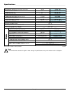
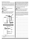
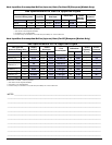
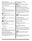
Warning (Gas Models Only – Export)
Dryers built for use with a voltage between 200
and 240 must verify the input voltage during
installation. If the nominal voltage is outside of the
medium tolerances shown on the diagram below, adjust
the autotransformers, located near the burner assemblies.
To adjust the autotransformer wiring, place the red wire on
the appropriate tap (HIGH, MED, LOW) of the
autotransformer. For additional wiring details, refer to the
electrical diagram located on the inside of the control
panel.
!
!
!
!
!
TERM
LINE VOLTAGE
50 Hz 60 Hz
HIGH
260
226
283
249
MED
239
208
260
230
LOW
217
189
236
208
!
Multiple Dryer Venting with 8-Inch (20.32 cm) Diameter
720 cfm (20.39 cmm) Exhaust Connections at Common Duct