


113413-11 Maytag Co. 15
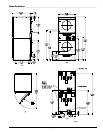
Piping/Connections
The dryer is provided with two 1/2” N.P.T. (3/8” B.S.P.T. for CE
dryers) inlet pipe connections (1 for each tumbler) at the rear
of the dryer. If a separate feed is provided for each tumbler
from the main supply line (header), then a 1/2” (12.7 mm)
line connection is sufficient. However, if the top and bottom
tumbler connections are connected together, the supply from
the header must be increased to 3/4-inch (19.05 mm). There
should be a minimum 6-inch (15.24 cm) clearance between
the back guard and the first bend in the gas piping for ease of
servicing. It is recommended that a gas shutoff valve be
provided to the gas supply line of each dryer for ease in
servicing.
The size of the main gas supply line (header) will vary
depending on the distance this line travels from the gas meter
or, in the case of L.P. gas, the supply tank, other gas-operated
appliances on the same line, etc. Specific information
regarding supply line size should be determined by the gas
supplier.
Note
Undersized gas supply piping can create a low or
inconsistent pressure, which will result in erratic
operation of the burner ignition system.
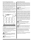
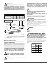
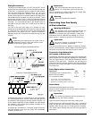
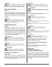
TYPICAL NATURAL GAS INSTALLATION
!
Consistent gas pressure is essential at all gas connections.
It is recommended that a 3/4-inch (19.05 mm) pipe gas loop
be installed in the supply line servicing a bank of dryers. An
in-line pressure regulator must be installed in the gas supply
line (header) if the (natural) gas pressure exceeds 13.0 in
WC (32.34 mb) pressure.
A plugged tap, accessible for a pressure gauge connection,
must be installed in the main gas supply line immediately
upstream of the dryers.
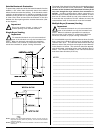
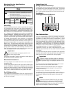
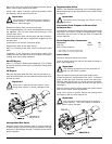
TYPICAL L.P. GAS INSTALLATION
!
!
Important
Pipe joint compounds that resist the action of
natural, L.P., and butane gases must be used.
Test all connections for leaks by brushing on a soapy water
solution (liquid detergent works well).
Warning
Never test for leaks with a flame!!!
Converting from One Family
of Gas to Another ______________________
Warning (CE Dryers)
This appliance must only be operated with the gas
type indicated on the dryer’s data plate. If the
appliance is converted (gas type changed), a data plate
amendment must be obtained from Maytag Co. (dryer’s
serial number is required to purchase a conversion kit).
Important
Any burner changes or conversions must be
made by a qualified professional.
The dryers manufactured for Belgium, Luxemburg, Greece,
Estonia, Slovak Republic, Iceland, Malta, Poland and Cyprus
cannot be converted from one family of gas to another.
Conversion from Natural Gas
to Propane or Butane Gas
The following conversion allows the dryer to be operated with
either propane gas or butane gas (regulated or unregulated).
The use of gas valve kit (P/N 140414) disables the internal
regulator of the gas valve. Therefore, the gas supply is
ungoverned and an external regulator must be provided at
the source of the supply (example L.P. tank) or the gas supply
line to the dryer.
Parts Required for Conversion:
Description P/N Qty
Unregulated Gas Conversion Kit*** 140414 2*
Burner Orifice (Injector) ** 2*
L.P. Conversion Label 114515 2*
* This includes 1 for each pocket/tumbler.
** Refer to page 14 for orifice (injector) size.
*** Required for unregulated propane or butane only.
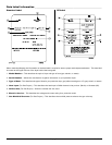
Instructions
Disconnect electrical power to the dryer.
Close all shutoff valves (for both top and bottom tumbler) in
dryer’s gas supply line.
Important
The following procedures must be performed on
both top and bottom tumblers.
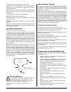
Open the panels located just below each loading door.
Locate the gas train and disconnect the union, 3 electrical
plugs, and the gas train mounting screws from the burner.
Carefully slide the gas train out of the gas train enclosure.
(The carbon ignitor located at the far end of the gas train is
very fragile.)
!
!
!