


12 Maytag Co. 113413-11
Gas Information _______________________
It is your responsibility to have all plumbing connections,
materials, and workmanship conform to local and state
regulations or codes of the country of destination. In the
absence of such codes, all plumbing connections, materials,
and workmanship must conform to the applicable local
requirements. In the USA this is the National Fuel Gas Code
ANSI Z223.1-LATEST EDITION, or in Canada, the Canadian
Installation Codes CAN/CGA-B149.1-M91 (Natural Gas) or
CAN/CGAB149.2-M91 (L.P. Gas) or LATEST EDITION.
In Australia, the fuel gas code is AS 5601/AG 601, local
authority, gas, electricity, and any other relevant statutory
regulations.
It is important that gas pressure regulators meet applicable
pressure requirements, and that gas meters be rated for the
total amount of all the appliance Btu being supplied.
Important
Failure to comply with these codes or ordinances,
and/or the requirements stipulated in this manual,
can result in personal injury and improper operation of the
dryer.
For ease of service, the individual gas supply line of each
dryer must have its own manual shutoff valve.
Failure to isolate or disconnect the dryer from supply as
noted can cause irreparable damage to the gas valve,
voiding the warranty.
The dryer and its individual shutoff valve must be
disconnected from the gas supply piping system during any
pressure testing of that system at test pressures in excess
of 1/2 psig (3.5 kPa) for non-CE dryers or 50 mb for CE
dryers.
Note
The dryer must be isolated from the gas supply
piping system by closing its individual manual
shutoff valve during any pressure test of the gas supply
system at test pressures equal to or less than 1/2 psig (3.5
kPa) for non-CE dryers or 50 mb for CE dryers.
!
!
!
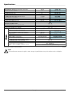
Electrical Service Specifications
Gas Models Only
Gas
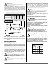
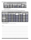
ELECTRICAL SERVICE SPECIFICATIONS (PER POCKET)
NOTES: A.
B.
When fuses are used they must be dual element, time delay, current
limiting, class RK1 or RK5 ONLY. Calculate/determine correct fuse
value, by applying either local and/or National Electrical Codes to
listed appliance amp draw data.
Circuit breakers are thermal-magnetic (industrial) motor curve type
ONLY. For others, calculate/verify correct breaker size according to
appliance amp draw rating and type of breaker used.
SERVICE
VOLTAGE
PHASE
WIRE
SERVICE
APPROX.
AMP DRAW
CIRCUIT
BREAKER
60 Hz 50 Hz
120 1ø 2 10.3 — 15
1/15/09
Grounding
A ground (earth) connection must be provided and installed
in accordance with local, state, and national regulations or
codes of the country of origin. In the absence of these codes,
grounding must conform to applicable requirements of the
National Electrical Code ANSI/NFPA NO. 70-LATEST EDITION,
or in Canada, the installation must conform to applicable
Canada Standards: Canadian Electrical Codes Parts 1 & 2
CSA C22.1-1990 or LATEST EDITION. The ground connection
may be to a proven earth ground at the location service panel.
For added personal safety, when possible, it is suggested
that a separate ground wire (size per local codes) be
connected from the ground connection of the dryer to a
grounded cold water pipe. Do not ground to a gas pipe or hot
water pipe. The grounded cold water pipe must have
metal-to-metal connection all the way to the electrical ground.
If there are any nonmetallic interruptions, such as, a meter,
pump, plastic, rubber, or other insulating connectors, they
must be jumped out with a wire (size per local codes) and
securely clamped to bare metal at both ends.
Important
For personal safety and proper operation, the
dryer must be grounded.
Provisions are made for ground connection in each dryer at
the electrical service connection area.
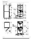
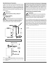
Electrical Connections
A wiring diagram is located behind the control panel for
connection data.
If local codes permit, power to the dryer can be made by the
use of a flexible UL listed power cord/pigtail (wire size must
conform to rating of dryer), or the dryer can be hard wired
directly to the service breaker panel. In both cases, a strain
relief must be installed where the wiring enters the dryer.
For CE Models Only
The means for disconnection from the supply must be
incorporated into wiring having a minimum contact separation
of 3.0 mm in all poles.
Single-Phase (1ø)
Wiring Connections/Hookup
The electrical input connections are made into the rear service
box located at the upper right area of the dryer. The ground
connection is made to the copper lug, also provided in this
box. To gain access, the service box cover must be removed.
Gas Models
120V Application with Neutral