


113376-4 Telephone 01422 822282 7
Installation Procedures ______________
Installation should be performed by competent technicians
in accordance with local and state codes. In the absence of
these codes, the installation must conform to applicable
American National Standards: ANSI Z223.1-LATEST
EDITION (National Fuel Gas Code) or ANSI/NFPA NO. 70-
LATEST EDITION (National Electrical Code) or in Canada,
the installation must conform to applicable Canadian
Standards: CAN/CGA-B149.1-M91 (Natural Gas) or CAN/
CGA-B149.2-M91 (L.P. Gas) or LATEST EDITION (for
General Installation and Gas Plumbing) or Canadian
Electrical Codes Parts 1 & 2 CSA C22.1-1990 or LATEST
EDITION (for Electrical Connections).
Location Requirements _______________
Before installing the dryer, be sure the location conforms to
local codes and ordinances. In the absence of such codes
or ordinances the location must conform with the National
Fuel Gas Code ANSI.Z223.1 LATEST EDITION, or in Canada,
the installation must conform to applicable Canadian
Standards: CAN/CGA-B149.1-M91 (Natural Gas) or CAN/
CGA-B149.2-M91 (L.P. Gas) or LATEST EDITION (for
General Installation and Gas Plumbing).
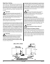
The dryer must be installed on a sound level floor capable of
supporting its weight. Carpeting must be removed from the
floor area that the dryer is to rest on.
Important
“The dryer must be installed on noncombustible
floors only.”
The dryer must not be installed or stored in an area where it
will be exposed to water and/or weather.
The dryer is for use in noncombustible locations.
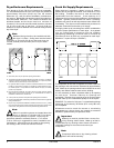
Provisions for adequate air supply must be provided as noted
in this manual (refer to Fresh Air Supply Requirements
section).
Clearance provisions must be made from combustible
construction as noted in this manual (refer to Dryer Enclosure
Requirements section).
Provisions must be made for adequate clearances for
servicing and for operation as noted in this manual (refer to
Dryer Enclosure Requirements section).
The dryer must be installed with a proper exhaust duct
connection to the outside as noted in this manual (refer to
Exhaust Requirements section).
The dryer must be located in an area where correct exhaust
venting can be achieved as noted in this manual (refer to
Exhaust Requirements section).
Important
The dryer should be located where a minimum
amount of exhaust duct will be necessary.
The dryer must be installed with adequate clearance for air
openings into the combustion chamber.
Caution
This dryer produces combustible lint and must be
exhausted to the outdoors. Every 6 months,
inspect the exhaust ducting and remove any lint buildup.
!
!
!
Important
The dryer must be installed in a location/
environment, which the ambient temperature
remains between 40° F (4.44° C) and 130° F (54.44° C).
Unpacking/Setting Up ________________
Remove protective shipping material (i.e. plastic wrap and
optional shipping box) from dryer.
Important
The dryer must be transported and handled in an
upright position at all times.
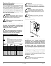
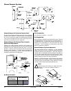
The dryer can be moved to its final location while still attached
to the skid or with the skid removed. To remove the skid
from the dryer, locate and remove the 4 lag bolts securing
the base of the dryer to the wooden skid. 2 are at the rear
base, and 2 are located in the bottom of the lint chamber. To
remove the 2 lag bolts located in the lint chamber area,
remove the lint drawer and the 3 Phillips head screws
securing the lint door in place.
Leveling Dryer
To level the dryer, place 4-inch (10.16 cm) square metal shims
or other suitable material under the base pads. It is suggested
that the dryer be tilted slightly to the rear.
The V-belts are disconnected from the tumbler drive motor
for shipping. Reconnect V-belts before starting the dryer.
If more headroom is needed when moving the dryer into
position, the top console (module) may be removed.
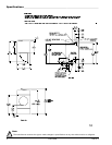
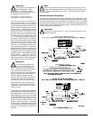
To Remove Top Console (Module)
Disconnect the ground wire (A in the illustration) located at
the rear upper left corner of the dryer.
Remove the 8 sets of nuts and washers (B in the illustration)
holding the console (module) to the base.
Disconnect the white plug connector (C in the illustration)
located on the top of the rear electric service/relay box
(provides power to the heat circuit).
Disconnect air connection from the 3-way micro valve.
Lift the console (module) off of the dryer base.
Important
The dryer must be transported and handled in an
upright position at all times.
!
!
!