


12 JLA Limited 113376-4
Important
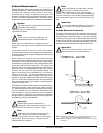
The dryer must be connected to the electric
supply shown on the data label. In the case of
208 VAC or 230/240 VAC, the supply voltage must match
the electric service specifications of the data label exactly.
Warning
208 VAC and 230/240 VAC are not the same.
Any damage done to dryer components due to
improper voltage connections will automatically void the
warranty.
Note
The manufacturer reserves the right to make
changes in specifications at any time without
notice or obligation.
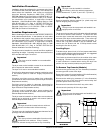
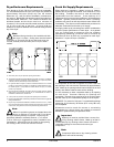
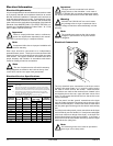
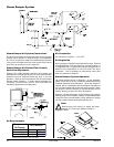
Electrical Connections
The only electrical input connections to the dryer are the
3-phase (3ø) power leads (L1, L2, and L3), ground, and in
the case of 4-wire service, the neutral. These electrical
connections are made at the terminal block located in the
service/relay box at the rear, upper left hand corner of the
dryer. To gain access into this service box, the service cover
must be removed.
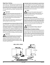
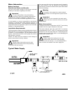
The “line power” and the “ground” connections to the dryer
must be made through the knockout hole at the top of the
electric service/relay box. A strain relief must be used where
the line power ground wires go into the electric service/relay
box.
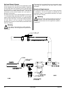
Providing local codes permit, power connections to the dryer
can be made by use of a flexible U.L. listed power cord/pigtail
(wire must conform to ratings of the dryer), or the dryer can
be hard wired directly to the service breaker. In all cases, a
strain relief must be used where the wire(s) enter the dryer
electrical service (relay) box.
Note
An individual ground circuit must be provided to
each dryer; do not daisy chain.
Electrical Information _________________
Electrical Requirements
It is your responsibility to have all electrical connections made
by a properly licensed and competent electrician to ensure
that the electrical installation is adequate and conforms to
local and state regulations or codes. In the absence of such
codes, all electrical connections, materials, and workmanship
must conform to the applicable requirements of the National
Electrical Code ANSI/NFPA NO. 70-LATEST EDITION or in
Canada, the Canadian Electrical Codes Parts 1 & 2 CSA
C22.1-1990 or LATEST EDITION.
Important
Failure to comply with these codes or ordinances,
and/or the requirements stipulated in this manual
can result in personal injury or component failure.
Note
Component failure due to improper installation will
void the warranty.
Each dryer should be connected to an independently
protected branch circuit. The dryer must be connected with
copper wire only. Do not use aluminum wire, which can create
a fire hazard. The copper conductor wire/cable must be of
proper ampacity and insulation in accordance with electric
codes for making all service connections.
Note
The use of aluminum wire will void the warranty.
Wiring diagrams are affixed to the inside at the top front
control door and the rear upper back guard/panel.
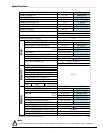
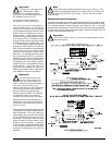
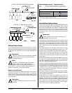
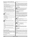
Electrical Service Specifications
* 3-Wire is available. 4/1/08
!
!
!
!
!
!
!
GAS AND STEAM
ELECTRICAL SERVICE SPECIFICATIONS (PER DRYER)
IMPORTANT:
NOTES
: A.
B.
C.
208 VAC AND 230/240 VAC ARE NOT THE SAME. When ordering, specify
exact voltage.
When fuses are used they must be dual element, time delay, current limiting,
class RK1 or RK5 ONLY. Calculate/determine correct fuse value, by applying
either local and/or National Electrical Codes to listed appliance amp draw data.
Circuit breakers are thermal-magnetic (industrial) motor curve type ONLY.
For others, calculate/verify correct breaker size according to appliance amp
draw rating and type of breaker used.
Circuit breakers for 3-phase (3Ø) dryers must be 3-pole type.
SERVICE
VOLTAGE
PHASE
WIRE
SERVICE
APPROX.
AMP DRAW
CIRCUIT
BREAKER
60 Hz 50 Hz
208 3ø 3 35.8 — 60
240 3ø 3 33.9 — 60
230 3ø 3 — 30.2 50
380 3ø 4* — 16.4 25
400 3ø 4* — 16.1 25
416 3ø 4* — 15.7 25
440 3ø 3 17.6 — 30
460 3ø 3 17.4 — 30
480 3ø 3 17.4 — 30
575 3ø 3 12.5 — 20