


24 JLA Limited 113376-4
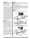
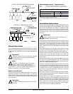
Input/Output Board Output Description
(“Green” L.E.D.)
1. FAN – This L.E.D. will indicate the status of the Fan output.
If the request to turn on the Fan (blower) is made, then the
L.E.D. is ON.
2. FWD – This L.E.D. will indicate the status of the Tumbler
Forward direction output. If the request to tumble the drum
in the Forward direction is made, then the L.E.D. is ON.
3. REV – This L.E.D. will indicate the status of the Tumbler
Reverse direction output. If the request to tumble the drum
in the Reverse direction is made, then the L.E.D. is ON.
4. AIR JET – This L.E.D. will indicate the status of the Air
Jet output. If the request to turn on the Air Jet is made, then
the L.E.D. is ON.
5. HEAT – This L.E.D. will indicate the status of the Front
Heat output. If the request to turn on the Front Burner is
made, then the L.E.D. is ON.
6. STEAM – This L.E.D. will indicate the status of the Steam
Injection output. If the request to turn on the Steam Injection
is made, then the L.E.D. is ON.
7. AUX – This L.E.D. will indicate the status of the Fire
Suppression System output. If the request to turn on the
Fire Suppression System is made, then the L.E.D. is ON.
Input/Output Board Input Description
(“Red” L.E.D.)
8. FUSE – This L.E.D. will indicate the status of the F2, which
fuses the 24 VAC supplied to the board.
9. LINT – This L.E.D. will indicate the status of the Lint
Drawer. If the drawer is closed, then the L.E.D. is ON.
10. MAIN – This L.E.D. will indicate the status of the Front
Doors. If the doors are closed, then the L.E.D. is ON.
11. EXHL – This L.E.D. will indicate the status of the Exhaust
Hi-Limit Disk. If the disk is closed (temperature below 225°
F [107° C]), then the L.E.D. is ON.
12. SAIL – This L.E.D. will indicate the status of the Sail
Switch. If the switch is closed, then the L.E.D. is ON.
13. BRHL – This L.E.D. will indicate the status of the Burner
Hi-Limit Disk. If the disk is closed (temperature below 330°
F [166° C]), then the L.E.D. is ON.
14. GAS_V – This L.E.D. will indicate the status of the Gas
Valve. If the Gas Valve is open (ON), then the L.E.D. is ON.
15. ESTOP – This L.E.D. will indicate the status of the
Emergency Stop Switch. If the Emergency Stop Switch is
open (ON), then the L.E.D. is ON.
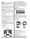
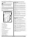
OUTPUTS: (GREEN)
1. FAN – Blower Fan On
2. FWD – Tumbler Forward
3. REV – Tumbler Reverse
4. AIR JET – Air Jet On
5. HEAT – Front Heat
6. STEAM – Steam Injection
7. AUX – Fire Suppression System Active On
INPUTS: (RED)
8. FUSE – 24 VAC To Board (F2)
9. LINT – Lint Drawer Closed
10. MAIN – Main Door Closed
11. EXHL – Exhaust High Limit
12. SAIL – Sail Switch
13. BRHL – Burner High Limit
14. GAS_V – Gas Valve
15. ESTOP – Emergency Stop
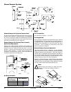
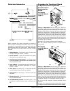
Phase 7 Non-Coin System Diagnostics
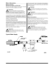
Important
You must disconnect and lockout the electric
supply and the gas supply or the steam supply
before any covers or guards are removed from the
machine to allow access for cleaning, adjusting,
installation, or testing of any equipment per OSHA
standards.
All major circuits, including door, microprocessor temperature
sensor, heat and motor circuits are monitored. The Phase 7
non-coin microprocessor controller (computer) will inform the
user, via the L.E.D. display of certain failure messages, along
with L.E.D. indicators on the input/output board on the back
panel of the front right control door.
Diagnostic (L.E.D. Display) Fault Messages
!