


14 JLA Limited 113376-4
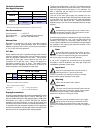
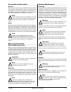
TYPE OF GAS
Btu/hr
Rating
kcal/hr
Rating
Natural Liquid Propane
Qty. D.M.S.* Part No. Qty. D.M.S.* Part No.
550,000
138,598
4 #2 140839 4 #30 140819
Liquid Propane Conversion Kit Part Number 883111
Technical Gas Data
Gas Specifications
Shaded areas are stated in metric equivalents
* Measured at the gas valve pressure tap when the gas valve is on.
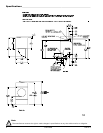
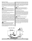
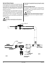
Gas Connections
Inlet connection ........ 1-1/2” F.P.T.
Inlet supply size ........ 1-1/2” Diameter Pipe (minimum)
Btu/hr input ............... 550,000 (138,598 kcal/hr)
Natural Gas
Regulation is controlled by the dryer’s gas valve’s internal
regulator. Incoming supply pressure must be consistent
between a minimum of 6.0 in WC (14.92 mb) and a maximum
of 12.0 in WC (29.9 mb) pressure.
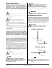
L.P. Gas
Dryers made for use with L.P. gas have the gas valve’s internal
pressure regulator blocked open so that the gas pressure
must be regulated upstream of the dryer. The pressure
measured at each gas valve pressure tap must be a
consistent 10.5 in WC (26.1 mb). There is no regulator or
regulation provided in an L.P. dryer. The water column
pressure must be regulated at the source (L.P. tank) or an
external regulator must be added to each dryer.
Shaded area is stated in metric equivalent
* D.M.S. equivalents are as follows:
Natural Gas.............................. #2 = 0.2210” (5.6134 mm).
L.P. Gas ...................................#30 = 0.1285” (3.2639 mm).
Piping/Connections
All components/materials must conform to National Fuel Gas
Code Specifications ANSI Z223.1-LATEST EDITION, or in
Canada, CAN/CGA-B149.1-M91 (Natural Gas) or CAN/CGA-
B149.2-M91 (L.P. Gas) or LATEST EDITION (for General
Installation and Gas Plumbing), as well as local codes and
ordinances and must be done by a qualified professional. It
is important that gas pressure regulators meet applicable
pressure requirements, and that gas meters be rated for the
total amount of all the appliance Btu being supplied.
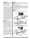
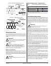
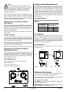
Type of Gas
Manifold Pressure* In-Line Pressure
Natural
3.5 inches W.C. 6.0-12.0 inches W.C.
8.7 mb 14.92 - 29.9 mb
Liquid
Propane
10.5 inches W.C. 11.0 inches W.C.
26.1 mb 27.4 mb
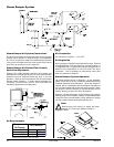
The dryer is provided with a 1-1/2” N.P.T. inlet pipe connection
extending out the back area of the burner box. The minimum
pipe size (supply line) to the dryer is 1-1/2” diameter. For
ease in servicing, the gas supply line of each dryer must
have its own shutoff valve.
The size of the main gas supply line (header) will vary
depending on the distance this line travels from the gas meter
or, in the case of L.P. gas, the supply tank, other gas-operated
appliances on the same line, etc. Specific information
regarding supply line size should be determined by the gas
supplier.
Note
Undersized gas supply piping can create a low or
inconsistent pressure, which will result in erratic
operation of the burner ignition system.
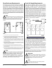
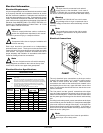
Consistent gas pressure is essential at all gas connections.
It is recommended that a 1-1/2” (3.81 cm) pipe gas loop be
installed in the supply line servicing a bank of dryers. An
in-line pressure regulator must be installed in the gas supply
line (header) if the (natural) gas pressure exceeds 12.0 in
WC (29.9 mb) pressure.
Note
A consistent water column test pressure of 3.5 in
WC (8.7 mb) for natural gas and 10.5 in WC (26.1
mb) for L.P. dryers is required at the gas valve pressure
tap of each dryer for proper and safe operation.
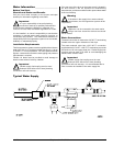
A 1/8” N.P.T. plugged tap, accessible for a test gauge
connection, must be installed in the main gas supply line
immediately upstream of each dryer.
Important
Pipe joint compounds that resist the action of
natural gas and L.P. gas must be used.
Test all connections for leaks by brushing on a soapy
water solution (liquid detergent works well).
Warning
Never test for leaks with a flame!!!
Important
The dryer and its individual shutoff valve must be
disconnected from the gas supply piping system
during any pressure testing of that system at test
pressures in excess of 1/2 psig (3.5 kPa).
Note
The dryer must be isolated from the gas supply
piping system by closing its individual manual
shutoff valve during any pressure test of the gas supply
system at test pressures equal to or less than 1/2 psig (3.5
kPa).
!
!
!
!
!
!