


10 JLA Limited 113376-4
All ductwork should be smooth inside with no projections from
sheet metal screws or other obstructions, which will collect
lint. When adding ducts, the duct to be added should overlap
the duct to which it is to be connected. All ductwork joints
must be taped to prevent moisture and lint from escaping
into the building. Inspection doors should be installed at
strategic points in the exhaust ductwork for periodic inspection
and cleaning of lint from the ductwork.
Note
When the exhaust ductwork passes through a
wall, ceiling, or roof made of combustible
materials, the opening must be 2-inches (5.08 cm) larger
than the duct (all the way around). The duct must be
centered within this opening.
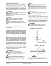
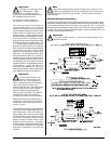
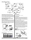
Outside Ductwork Protection
To protect the outside end of the horizontal ductwork from
the weather, a 90° elbow bent downward should be installed
where the exhaust exits the building. If the ductwork travels
vertically up through the roof, it should be protected from the
weather by using a 180° turn to point the opening downward.
In either case, allow at least twice the diameter of the duct
between the duct opening and the nearest obstruction.
Important
Do not use screens, louvers, or caps on the
outside opening of the exhaust ductwork.
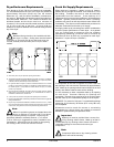
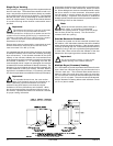
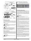
Multiple Dryer (Common) Venting
If it is not feasible to provide separate exhaust ducts for each
dryer, ducts from individual dryers may be channeled into a
“common main duct.” The individual ducts should enter the
bottom or side of the main duct at an angle not more than
45° in the direction of the flow and should be spaced at least
55-3/4” (141.61 cm) apart. The main duct should be tapered,
with the diameter increasing before each individual 18-inch
(45.72 cm) duct is added.
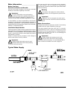
Single Dryer Venting
When possible, it is suggested to provide a separate exhaust
duct for each dryer. The exhaust duct should be laid out in
such a way that the ductwork travels as directly as possible
to the outdoors with as few turns as possible. It is suggested
that the use of 90° turns in the ducting be avoided; use 30°
and/or 45° angles instead. The shape of the exhaust ductwork
is not critical as long as the minimum cross section area is
provided.
Important
The minimum duct size for a gas unit is 18-inches
(45.72 cm) for a round duct and 16-inches x
16-inches (40.64 cm x 40.64 cm) for a square duct and for
a steam unit is 20-inches (50.80 cm) for a round duct and
18-inches x 18-inches (45.72 cm x 45.72 cm) for a square
duct. The duct size must not be reduced anywhere
downstream of the dryer.
Exhaust back pressure measured by a manometer at each
tumbler exhaust duct area must be no less than 0 and
must not exceed 0.3 in WC (0.74 mb).
It is suggested that the ductwork from each dryer not exceed
20 feet (6.09 meters) with no more than 2 elbows (excluding
dryer connections). If the ductwork exceeds 20 feet (6.09
meters) or has numerous elbows, the cross-sectional area
of the ductwork must be increased in proportion to the length
and number of elbows in it. In calculating duct size, the
cross-sectional area of a square or rectangular duct must be
increased 20% for each additional 20 feet (6.09 meters). The
diameter of a round exhaust duct should be increased 10%
for each additional 15 feet (4.57 meters). Each 90° elbow is
equivalent to an additional 40 feet (12.19 meters), and each
45° elbow is equivalent to an additional 20 feet (6.09 meters).
Important
For extended ductwork runs, the cross section
area of the ductwork can only be increased to an
extent. Maximum proportional ductwork runs cannot
exceed 20 feet (6.09 meters) more than the original
limitations of 20 feet (6.09 meters) with 2 elbows. When
the ductwork approaches the maximum limits as noted in
this manual, a professional HVAC firm should be consulted
for proper venting information.
!
!
!
!