


50
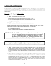
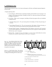
2. Information entered is sent to the microcontroller via the keyboard.
3. The input information is sorted/processed and executed by the microcomputer chip.
4. The microcomputer output signal activates the contactors and DSI module which control machine functions.
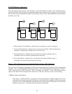
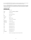
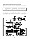
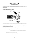
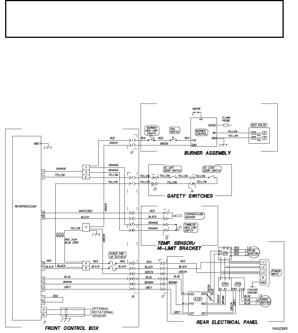
NOTE: When contacting ADC with electrical questions, please have on hand the correct
wiring diagram number for your particular machine. This number is located on the
top right-hand corner of the diagram. It is a six (6) digit number followed by a
letter to distinguish the revision dates (see illustration).
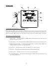
The wiring diagrams used in Troubleshooting are specifically for dryers manufactured at the time of publishing.
Your particular model may vary slightly depending on the date of manufacturing and options available. The
correct wiring diagram and number is either taped to the rear of the control door on each dryer, or placed in the
control box. If your particular diagram is lost or unreadable, call ADC with the serial number of the dryer. ADC
will be more than happy to send you a diagram by fax or mail.