


43
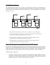
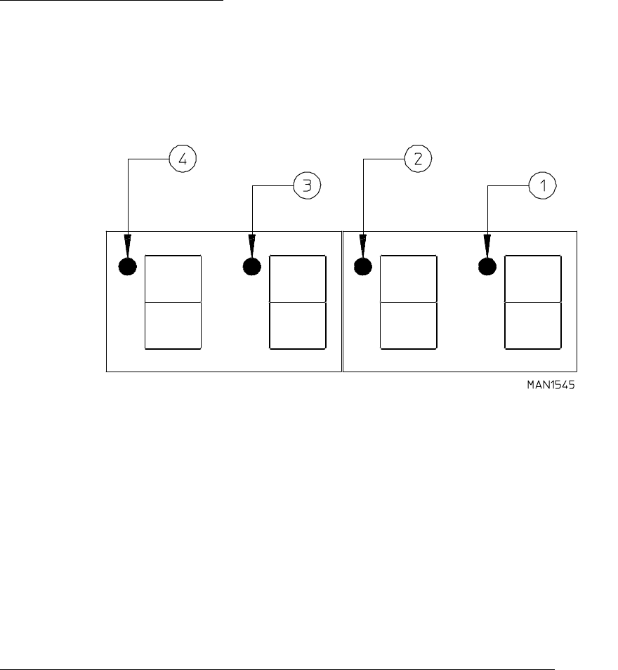
1. Blower Motor Circuit Indicator - indicator dot is on whenever a cycle is in progress.
2. Heat Controller Indicator - indicator dot is on whenever the Phase 5 OPL microprocessor
controller is calling for the heating circuit to be active (on).
3. Reversing Indicator - indicator dot is on when the drive basket (tumbler) motor is
operating in the reverse mode (counterclockwise direction).
4. Reversing Indicator - indicator dot is on when the drive basket (tumbler) motor is
operating in the forward mode (clockwise direction).
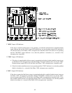
Phase 5 OPL Microprocessor Controller Relay Output LED Indicators
There are five (5) LED indicators (red lights) located at the lower backside area of the Phase 5 OPL microprocessor
controller. They are identified/labeled (from left to right as shown in the illustration on this page) as "HEAT",
"MTR" (blower motor), "FWD" (forward), "REV" (reversing), and "DOOR". These LEDs indicate that the
outputs of the Phase 5 OPL microprocessor controller or, in the case of the door switch, are functioning.
1. "HEAT" Output LED Indicator -
If the dryer is started and there is no heat, yet the microprocessor controller display heat circuit
indicator dot is on, but the heat output LED indicator is off, then the fault is in Phase 5 OPL microprocessor
controller itself. If both display heat indicator dot and the heat output LED indicator are on, then the
problem is elsewhere (i.e., external of the microprocessor controller).
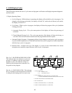
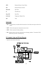
B. LED Display Indicators
The LED indicator dots located at the top portion of the LED display (as shown in the illustration below)
indicate the Phase 5 OPL microprocessor controller output functions while a cycle is in progress. These indicator
dots do not necessarily mean that the outputs are functioning. They are only indicating that the function (output)
should be active (on).