Page 8 of 24 Rev: 1/21/2014 7:36 AM
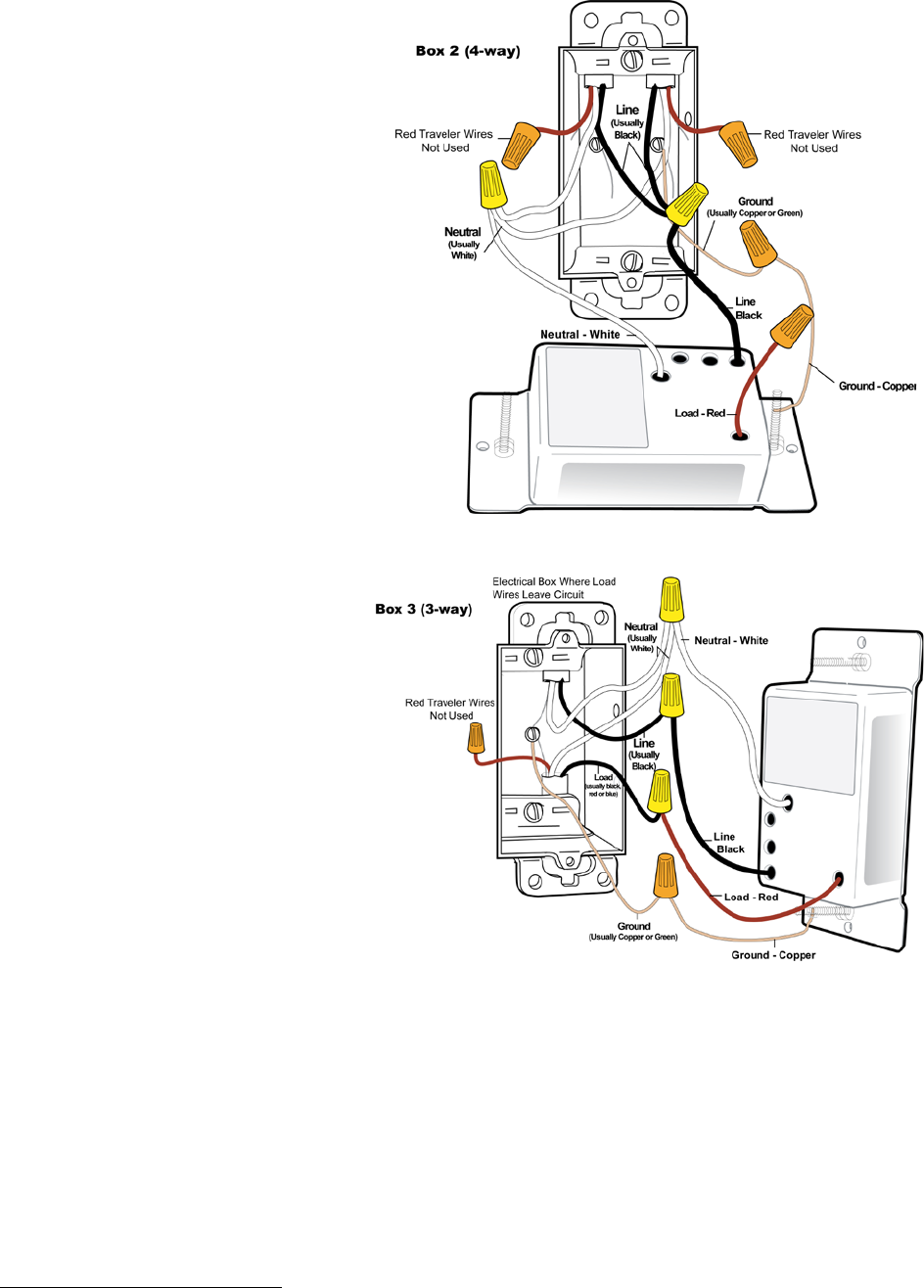
In Box 2 (Traveler box)
12) Connect bare Ground wire from
KeypadLinc to bare Ground wire or
Ground screw in wall box
13) Connect White Neutral wire from
KeypadLinc to Neutral wire(s) in
wall box (usually White)
1
14) Cap Red wire from KeypadLinc
15) Connect Black wire from
KeypadLinc to same color Traveler
from box 1 that you connected to
Line along with same color
Traveler wires leading to box 3
16) Cap the last unused Traveler
wire(s)
In Box 3 (Load box)
17) Connect bare Ground wire from
KeypadLinc to bare Ground wire
or Ground screw in wall box
18) Connect White Neutral wire from
KeypadLinc to Neutral wires(s)
in wall box (usually White)
19) Connect Red wire from
KeypadLinc to Load wire
(usually Black)
20) Connect Black wire from
KeypadLinc to Line Traveler
from box 2 (Line Traveled from
box 1 through 2 into 3 usually
Black)
21) Cap unused Traveler wire
22) With button labels right-side up,
gently place KeypadLincs into
wall boxes and screw in place
23) Turn power back On
KeypadLinc’s On button and connected light will turn on
Only KeypadLinc in box 3 will operate the load until you synchronize Scenes on the 3
devices
24) Add each KeypadLincs to a Scene as a Controller and Responder of each other (see
Synchronized Scenes)
22) Verify all KeypadLincs are working properly by tapping On and Off on a 6 button KeypadLinc or
MAIN On and Off on an 8 button KeypadLinc turning connected light on and off
25) Reinstall wallplates
1
If Neutral is not available in this box; use other unused Traveler from box 1 to carry Neutral to box 2. Label and mark any differently colored wire being connected to Neutral
with a piece of white tape to flag it as Neutral.


