Page 7 of 24 Rev: 1/21/2014 7:36 AM
16) Cap unused Traveler wire
17) With button labels right-side up, gently place KeypadLincs into wall boxes and screw in place
18) Turn power back on
KeypadLinc’s On button and connected light will turn on
Only KeypadLinc in box 2 will operate the Load until you synchronize Scenes to the 2
devices
19) Add both KeypadLincs to a Scene as a Controller and Responder of each other (see
Synchronized Scenes)
20) Verify both KeypadLincs are working properly by tapping On and Off on a 6 button KeypadLinc or
MAIN On and Off on an 8 button KeypadLinc turning connected light on and off
21) Reinstall wallplates
Installation – Circuit with 3 (or more) Switches
Circuits with 3 or more switches are called 3-way/4-way circuits. All switches in 3-way/4-way circuits need
to be replaced by KeypadLincs (and/or SwitchLincs).
Note: 3-way/4-way circuits require a pair of wires called Travelers between joining wall boxes to operate.
INSTEON switches, dimmers and keypads do not require both Traveler wires for 3-way/4-way circuits to
function. Simply wire one to Line, Neutral and Load; the other(s) to Line and Neutral. Use one Traveler to
share Line between boxes. Adding to a Scene creates a virtual 3-way/4-way circuit. The following
example shows three switches.
1) Turn off circuit breaker(s) and/or remove fuse(s) feeding wall boxes (verify that power is off)
2) Pull all three switches from their wall boxes, each existing 3-way switch will have a minimum 3
wires; 4-way switches will have 4 wires
3) Remove wires from existing switches
4) Make sure wires are safely separated from each other and turn power back on
5) Using a voltage meter measure each wire to Ground in all three boxes until you find the single
wire supplying 120V (Line)
a. We will now refer to that location as box 1
b. The location having 2 sets of matching pairs of wires will be box 2 (i.e. 2 Reds and 2
Blacks, or other matching colors). These are 2 Travelers from box 1 and 2 Travelers
leading to box 3.
c. The last box will have the Load wire, that will be box 3
6) Turn power back off
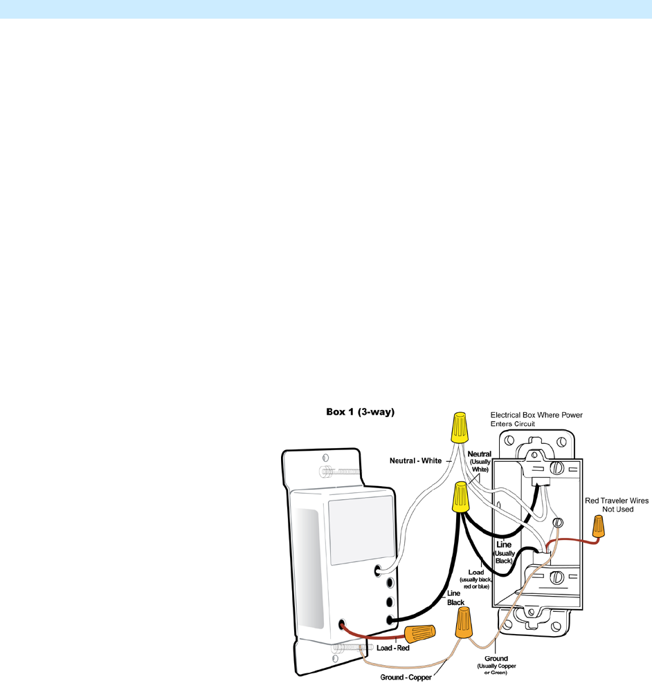
In Box 1 (Line box)
7) Connect bare Ground wire from
KeypadLinc to bare Ground wire or
Ground screw in wall box
8) Connect White Neutral wire from
KeypadLinc to Neutral wire(s) in
wall box (usually White)
9) Cap Red wire from KeypadLinc
10) Connect Black wire from
KeypadLinc to 120V Line wire in
wall box (usually Black) along with
one Traveler wire running between
boxes (preferably Black). Note
color of Traveler you are using as
this will carry Line voltage to box 2
11) Cap unused Traveler wire


