71
and substituting the appropriate values in the
formulabelow,determinewhatthegasow
should be in this 3 minute period to give the
input shown on the Rating Plate:
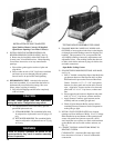
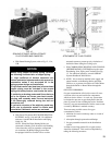
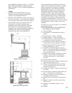
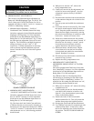
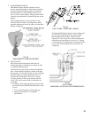
(c) ADJUST AIR SHUTTERS – See Section V
Burners are normally shipped with the air
shutters in the wide open position. Loosen air
shutter securing screws and close air shutters
untilyellowtipsappearonames,thenopen
shuttersslowlyuntildenedinnerconesmay
be seen. Lock shutters in this position.
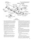
(d) ADJUST BLEED LINE REGULATOR
(V88A’s)
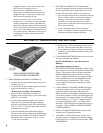
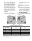
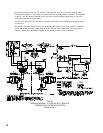
All gas boilers for the USA and Canada are
normally equipped with two diaphragm gas
valves per manifold. The gas valve(s) nearest
the manifold on all boilers, is equipped with an
adjustable bleed. This bleed regulator should
beadjustedsothattheburnersreachfullre
inapproximately10-12secondsafterthemain
gas valves have been energized.
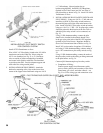
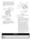
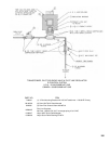
(e) ADJUST PILOT LINE PRESSURE – See
Section V - Service; 7. Pilot Flame
Shut down boiler and remove gas valve and
manometer from 1/8” pipe tapping in each
manifold. Plug tappings with square head pipe
plugs. Install gas valve in tee in each pilot line.
Connect manometer to each gas valve and, with
boiler in operation, set pilot line pressure at
5.5”water–naturalgasboilersand6.5”water
– propane gas boilers.
Shut boiler down, remove gas valves and
manometers and plug tees with square head
pipe plugs. Restart boiler.
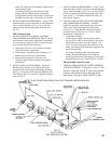
14. CHECK GAS INPUT RATE TO BOILER
(1)InputRateandMaximumInletPressureshownon
RatingPlatemustnotbeexceeded.Inletpressure
must not be lower than minimum inlet pressure
shown on Rating Plate.
(2) All Rate checks and all adjustments are to be
madewhileboilerisring–allotherappliances
connected to the same meter as the boiler must be
off.
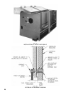
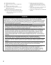
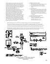
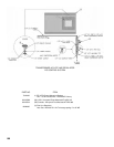
(3) Water Manometer or water column gauge should
be connected to a shut-off valve installed in the
1/8” pipe tapping in each manifold – boiler off. By
installing gas valve upstream of manometer, gas
pressure can be introduced gradually – without
shut-off valve, surge of pressure when boiler is
turned on, could blow liquid out of manometer.
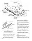
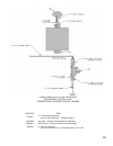
(4) LP Gas Input
(a) Adjust Gas Train Regulator(s) so that manifold
pressureisten(10)incheswatercolumn.
Turning Regulator Adjusting Screw Clockwise
increases pressure, Counterclockwise rotation
decreases pressure. If boiler is equipped with
twomanifolds(5015Bthru5026B),pressure
in each must be equal.
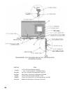
(5) Natural Gas Input
(a)ApproximateInput–AdjustGasTrain
Regulator(s) so that manifold pressure is three
and a half (3½) inches from water column.
Turning Regulator Adjusting Screw Clockwise
increases pressure, Counterclockwise rotation
decreases pressure. If boiler is equipped with
two manifolds, pressure in each must be equal.
If more accurate check on input is necessary,
see (b) below.
For minor input changes readjust Gas Train
Regulator(s) to increase or decrease manifold
pressure to obtain corresponding increase or
decrease in gas input. If it is necessary to
increasemanifoldpressuremorethan0.3”of
watertoobtainratedinput,removeorices
and drill one size larger. Reinstall and recheck
input rate.
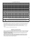
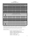
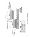
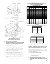
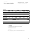
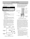
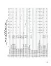
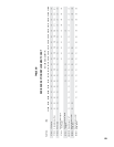
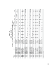
(b) Additional Check on Input – Since input is
afunctionofheatingvalue,specicgravity
andvolumeofgasowcontactyourutility
forthersttwoitemsinordertoutilizethe
formula below. The gas meter should then be
clocked for three (3) minutes with stop watch
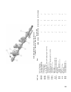
cu. ft. per =
3 min.
Btuh Input
Heating x 20 x multiplier
Value
of gas
(from
table
below)
(Btu/cuft)
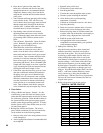
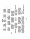
spec. gravity multiplier
.50 1.10
.55 1.04
.60 1.00
.65 0.96
.70 0.93