19
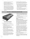
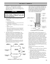
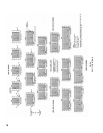
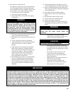
1. Repairing system leaks to eliminate the need for
addition of make-up water.
2. Eliminating open tanks from the system.
3.Eliminatingand/orrepairingttingswhichallow
oxygenabsorption.
4. Use of non-permeable materials in the distribution
system.
5. Isolating the boiler from the system water by
installingaheatexchanger.
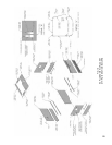
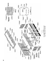
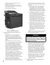
Open Jacket Parts Carton
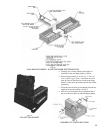
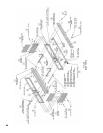
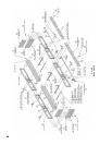
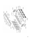
15. INSTALLATION OF JACKET PARTS COMMON TO
ALL BOILER SIZES
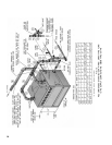
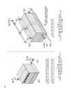
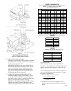
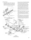
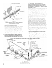
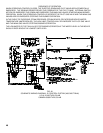
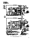
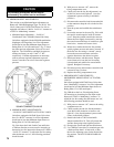
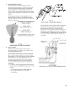
1. Attach Lower Jacket End Panel Support Bracket to
BaseEndPanel(Bothends)using¼”-20x½”self-
tappingscrews,seeFig.2and16.
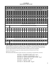
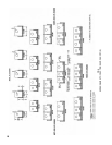
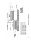
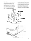
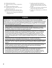
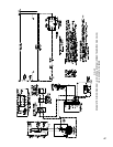
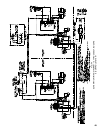
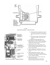
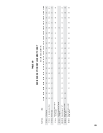
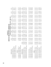
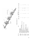
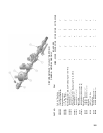
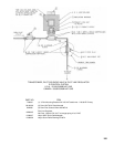
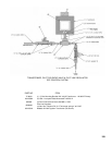
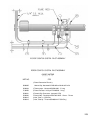
FIG. 15
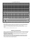
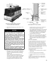
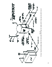
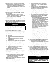
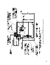
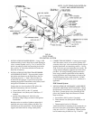
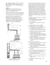
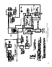
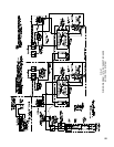
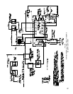
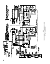
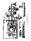
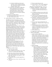
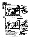
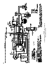
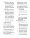
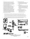
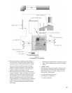
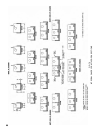
RECOMMENDED BOILER PIPING FOR
COMBINATION HEATING & COOLING SYSTEMS
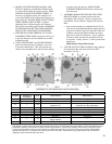
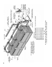
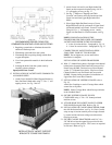
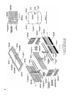
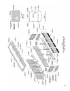
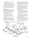
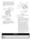
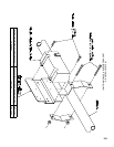
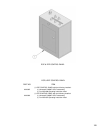
2. Attach Lower Left and Lower Right Jacket End
Panelstotheirrespectivebracketsusing#10-32x
½” self-tapping screws, see Fig. 17.
3. See Fig. 7 “Purpose of Tappings and Their
Location” and remove necessary knockouts from
Upper Left and from Upper Right Jacket End
Panels.
4. Place Upper Right End Panel on top of Lower
Right End Panel with lip on bottom of Upper Panel
positioned behind Lower Panel. Secure to section
using#10-32x½”self-tappingscrews.Attach
Upper Left End Panel in a similar manner, see Fig.
17.
NOTE: FOR INSTALLATION OF THE
FRAMEWORK FOR THE LOWER UNCOMMON
JACKET PARTS REFER TO THE FOLLOWING:
a.6thru10sectionboilers–Paragraph16,Fig.19
b.11thru26sectionboilers–Paragraph30,Fig.23
COMPLETION OF JACKET INSTALLATION –
5006BTHRU5010BSECTIONBOILERS
NOTE: Do not tighten any screws until Jacket
installation is complete.
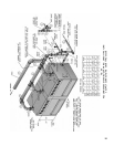
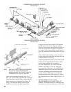
INSTALLATION OF LOWER FRAMEWORK
16. With“U”channelfacingdown,slipupperfrontchannel
behind joints formed by End Panels and secure to End
Panels using #8 SMS. Position Lower Front Channel
so that “U” of channel faces boiler. Slip Lower Front
Channel behind Lower End Panels and secure with
#8 SMS. Repeat similar procedure for installation of
Upper Rear and Lower Rear Channels.
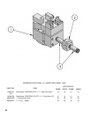
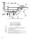
17. INSTALLATION OF VESTIBULE PANEL refer to
Fig. 18.
AttachHexCouplingstoendofCarriageBoltswhich
secureuecoverplates.
NOTE: Select Carriage Bolts which line up with holes
in the Vestibule Panel.
18. SECURE VESTIBULE PANEL TO HEX
COUPLINGSusing¼”-20x3/8”slottedpanhead
machine screws.
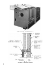
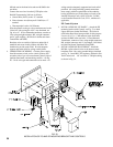
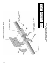
19. ATTACH REAR TOP JACKET PANEL TO UPPER
END PANELS using #8 SMS. Refer to Fig. 19.
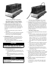
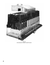
20. INSTALLATION OF CANOPY-DRAFTHOOD5006B
thru5010BSectionBoilers,seeFig.20.PlaceCerafelt
stripsontopofsectionassemblynexttoledgesformed
bycentersectionsandnexttoledgeonendsections.
Overlap at corners.
21. SECURE CANOPY-DRAFTHOOD with5/16”-18x
5/8” MS driven into the tapped lugs provided for this
purpose on top of the sections. Two screws are required
at each end. Refer to Fig. 21.
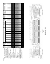
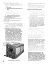
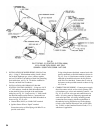
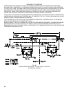
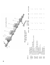
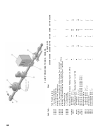
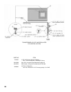
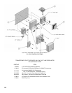
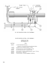
FIG. 16
INSTALLATION OF JACKET SUPPORT
BRACKETS TO BASE END PANELS