37
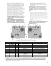
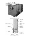
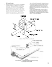
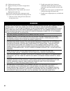
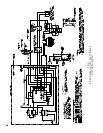
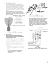
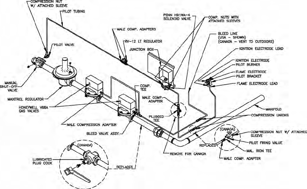
3. INSTALLATION OF BLEED PIPING – Using ¼” OD
aluminum tubing, install a bleed line on both diaphragm
valves,connecttogether,seeFig.25or26,and,onUSA
boilers, run tubing to bleed line protruding from inside
base, see Fig. 34. On boilers installed in Canada, run
bleed line to outdoors.
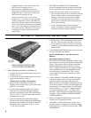
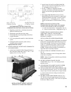
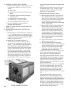
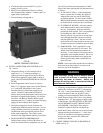
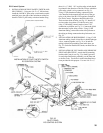
4. INSTALLATION OF IGNITION TRANSFORMER
AND WIRING OF PILOT – If space permits, mount
the ignition transformer on the Jacket above the Gas
Trainusingfour#8x½”SMS.Holeswillhaveto
be drilled for this purpose. If space does not permit
mounting the Ignition Transformer on the Jacket, install
the Ignition Transformer on a nearby wall.
Connect the two wires from the Q179C pilot to the
RA890FProtectorelaySubbaseasfollows:
a.GroundWire(200ºC)tothe“G”terminal
b.Flamedetectorwire(Honeywell1298020)to“F”
terminal
c. IgnitionCable(Honeywell1061012)tothe
Secondary (High Voltage) terminal of the Ignition
Transformer
Run these wires to outside of jacket on underside of
manifold and secure in this position with Wire Ties
furnished to provide strain relief. Provide adequate
support and strain relief for wiring outside jacket.
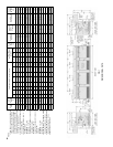
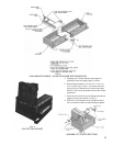
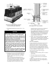
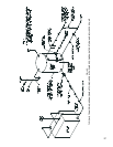
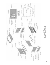
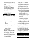
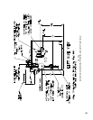
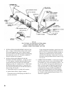
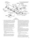
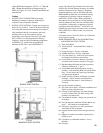
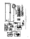
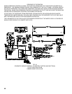
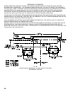
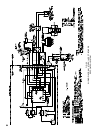
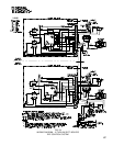
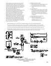
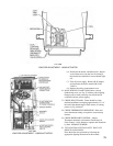
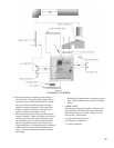
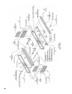
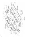
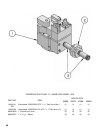
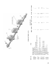
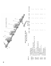
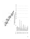
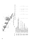
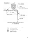
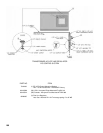
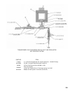
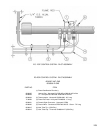
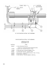
FIG. 34
PILOT PIPING
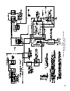
EE CONTROL SYSTEM
NOTE - PILOT PIPING DUPLICATED ON
15 SECT. AND LARGER BOILERS.
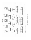
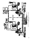
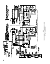
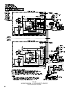
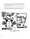
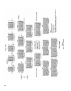
5. COMPLETION OF WIRING – Connect power supply
fused disconnect switch, service switch, primary and
secondary side of gas valve transformer, primary side of
ignition transformer, and remaining controls – see Fig.
48
&50forwiretypeandconnectionstobemade.All
wiring must be adequately supported and strain relief
provided. All wiring including ground connections
must comply with the requirements of the authority
having jurisdiction and, in the absence of such, to the
NationalElectricalCode,ANSINFPANo.70-2005,
or the Canadian Electrical Code, C22.1, whichever is
applicable.
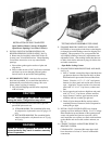
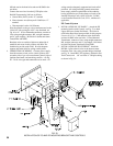
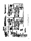
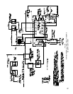
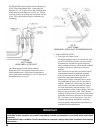
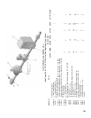
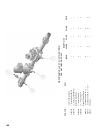
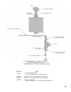
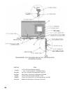
EOP Control System
1. INSTALLATION OF “EOP PANEL” AND WIRING
OF PILOT AND PILOT SAFETY SWITCH – Mount
the Electronic Control Panel on a wall adjacent to the
Gas Train. Connect the two wires from the Q179D
pilot to the Terminal Strip in the Electronic Control
Panel as follows:
a.GroundWire(200ºC)tothe#12terminal
b.Flamedetectorwire(Honeywell1298020)to#11
terminal
c. ThermocoupleLeadtoL62Pilotstat.
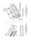
Attachthebracketformountingofthejunctionboxto
the lower front corner of the Jacket Upper End Panel
usingtwo#10-32x½”MSandnuts.Mountjunction
boxtobracketusing#8SMS,seeFig.25and26.