


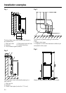

Installation - venting
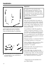
The shortest passage for the expelled
air is preferable, to ensure the tumble
dryer functions most efficiently. Ex-
pelled air is slowed down in the vent
duct due to friction against the inner
walls of the duct, therefore the shorter
the duct and the smoother the inner
walls, the less friction occurs.
An elbow or bend creates more friction
than a straight duct. An additional duct
length factor should therefore be calcu-
lated for each elbow or bend (see
Table I). This factor expresses the re-
sistance of the bend in terms of a
straight length of duct.
The additional length factor is then
added to the actual duct length to give
the effective duct length.
A larger duct diameter also helps to re-
duce friction. The duct diameter should
therefore increase with increasing duct
length.
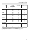
Table I
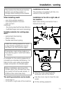
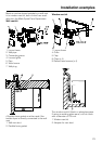
To calculate the effective duct length.
Measure the actual duct length. Es-
tablish the number of elbows or
bends necessary, noting the type of
bend, angle and radius involved
(see Table I).
Add the additional length factor as
specified in Table I to the actual duct
length to give the effective duct
length.
The appropriate duct diameter can
then be taken from Table II.
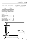
Note:
Drying times and energy consumption
remain unaltered for 100 mm ducting
up to a total duct length of 10 m.
Longer ducting may lead to slight in-
creases in drying times and energy
consumption but does not impair the
function of the machine, if the necess-
ary duct diameter is adhered to (see
Table II).
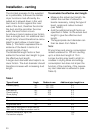
Type of bend Angle Radius in mm Additonal pipe lenght in m
Flexible piping 90°
45°
100 - 500
100 - 500
0.5
0.4
Plain piping
Plastic piping
Stove piping
90°
90°
45°
100
200
100
0.4
0.3
0.3
Elbow 2.5
Concertina bend 90° 200 0.8
Segmented bend 90° 200 0.6
Wall vent kit with grille or windo vent kit
Wall vent kit with flap or window vent kit
3.8
1.5
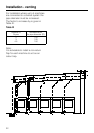
Exhaust connection, right / left
Flat section adaptor
10/6
18
20