


13
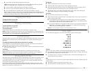
Vent system chart
NOTE: Side and bottom exhaust installations have a 90º turn inside the dryer. To determine
maximum exhaust length, add one 90º turn to the chart.
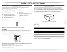
Install Vent System
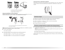
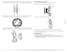
1. Install exhaust hood. Use caulking compound to seal exterior wall opening around
exhaust hood.
2. Connect vent to exhaust hood. Vent must fit inside exhaust hood. Secure vent to exhaust
hood with 4" (10.2 cm) clamp.
3. Run vent to dryer location. Use the straightest path possible. See “Determine vent path” in
“Plan Vent System.” Avoid 90º turns. Use clamps to seal all joints. Do not use duct tape,
screws or other fastening devices that extend into the interior of the vent to secure vent.
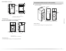
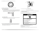
Install Leveling Legs
1. To protect the floor, use a large flat piece of cardboard from the dryer carton. Place
cardboard under the entire back edge of the dryer.
2. Firmly grasp the body of the dryer. Gently lay the dryer on the cardboard. See illustration.
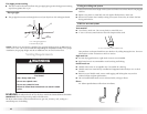
3. Examine the leveling legs. Find the diamond marking.
4. Screw the legs into the leg holes by hand. Use a wrench to finish turning the legs until the
diamond marking is no longer visible.
5. Place a carton corner post from dryer packaging under each of the 2 dryer back corners.
Stand the dryer up. Slide the dryer on the corner posts until it is close to its final location.
Leave enough room to connect the exhaust vent or gas line.
For mobile home use
Gas dryers must be securely fastened to the floor at the time of installation.
Mobile home installations require a Mobile Home Installation Kit. For more information,
please reference the service numbers in the “Assistance or Service” section.
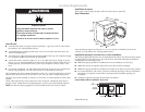
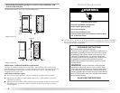
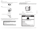
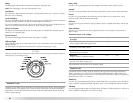
Make Gas Connection
1. Remove the red cap from the gas pipe.
2. Using a wrench to tighten, connect the gas supply to the dryer. Use pipe-joint compound
on the threads of all non-flared male fittings. If flexible metal tubing is used, be sure there
are no kinks.
Number of 90º
turns or elbows
Type of vent Box or louvered
hoods
Angled hoods
0 Rigid metal
Flexible metal
64 ft (20 m)
36 ft (11 m)
58 ft (17.7 m)
28 ft (8.5 m)
1 Rigid metal
Flexible metal
54 ft (16.5 m)
31 ft (9.4 m)
48 ft (14.6 m)
23 ft (7 m)
2 Rigid metal
Flexible metal
44 ft (13.4 m)
27 ft (8.2 m)
38 ft (11.6 m)
19 ft (5.8 m)
3 Rigid metal
Flexible metal
35 ft (10.7 m)
25 ft (7.6 m)
29 ft (8.8 m)
17 ft (5.2 m)
4 Rigid metal
Flexible metal
27 ft (8.2 m)
23 ft (7 m)
21 ft (6.4 m)
15 ft (4.6 m)
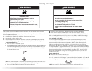
WARNING
Excessive Weight Hazard
Use two or more people to move and install dryer.
Failure to do so can result in back or other injury.
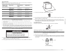
A. Flared male fitting
B. Non-flared male fitting
A
B