


18 16022785 Rev. 0 ©2003 Maytag Appliances Company
Troubleshooting Procedures
!
WARNING
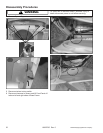
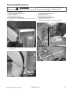
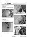
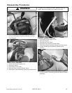
To avoid risk of electrical shock, personal injury or death, disconnect power to unit before servicing, unless testing
requires power.
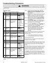
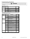
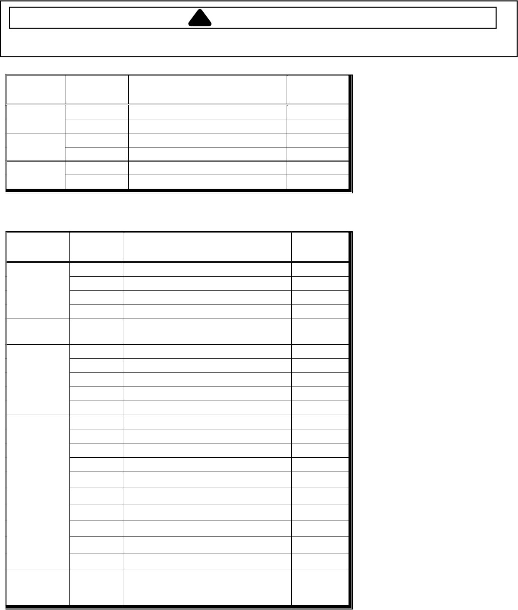
Relay Header Connections
Relay
Name
Connector
Name
Description Voltage
NO L1 to relay 120 VAC K9
COM L1 to lower dryer motor 120 VAC
NO L1 to relay 240 VAC K8
COM L1 to lower dryer heater center tap 240 VAC
NO L1 to relay 240 VAC K7
COM L1 to lower dryer 240 VAC
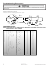
Power and Relay Board Connectors
Connector
Name
Pin
Number
Description Voltage
1 L1 to shaker motor 120 VAC
2 L1 to upper cabinet lamp 120 VAC
3 Neutral to shaker & lamp assembly 120 VACN
J5
4 Unassigned
J6B 1-12
See J6A in Logic Board
Connectors Table
5 & 12
VDC
1 Neutral to Power & Relay Board 120 VACN
2 L2 to Power & Relay Board 120 VAC
3 Gas Igniter Sense 120 VAC
4 Lower Door Switch 120 VAC
J7
5 L1 to Power & Relay Board 120 VAC
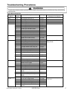
1 Relay to upper blower motor 120 VAC
2 Unassigned
3 Unassigned
4 Unassigned
5
Relay connects upper heater to L2
120 VAC
6
Relay to upper dryer damper
120 VAC
7
Spare relay output
120 VAC
8
Relay to water valve
120 VAC
9
Unassigned
J9
10
Relay connects upper heater to L2
120 VAC
J11B
1-5
See J11A in Logic Board
Connectors table (Pin #3 is not
used).
120 VAC
Note: VACN is the neutral wire of a 120V supply.