


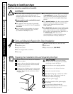
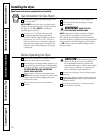
Remove the screws securing the terminal block
access cover and the strain relief mounting
bracket located on the back of the dryer
upper corner.
Install a UL-approved strain relief into the power
cord entry hole of the mounting bracket. Use
a strain relief which attaches to the mounting
bracket with a nut. Finger-tighten the nut only
at this time.
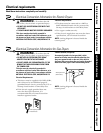
Thread a UL-approved 30A, 240V, 3 #10 AWG
minimum copper conductor power cord through
the strain relief.
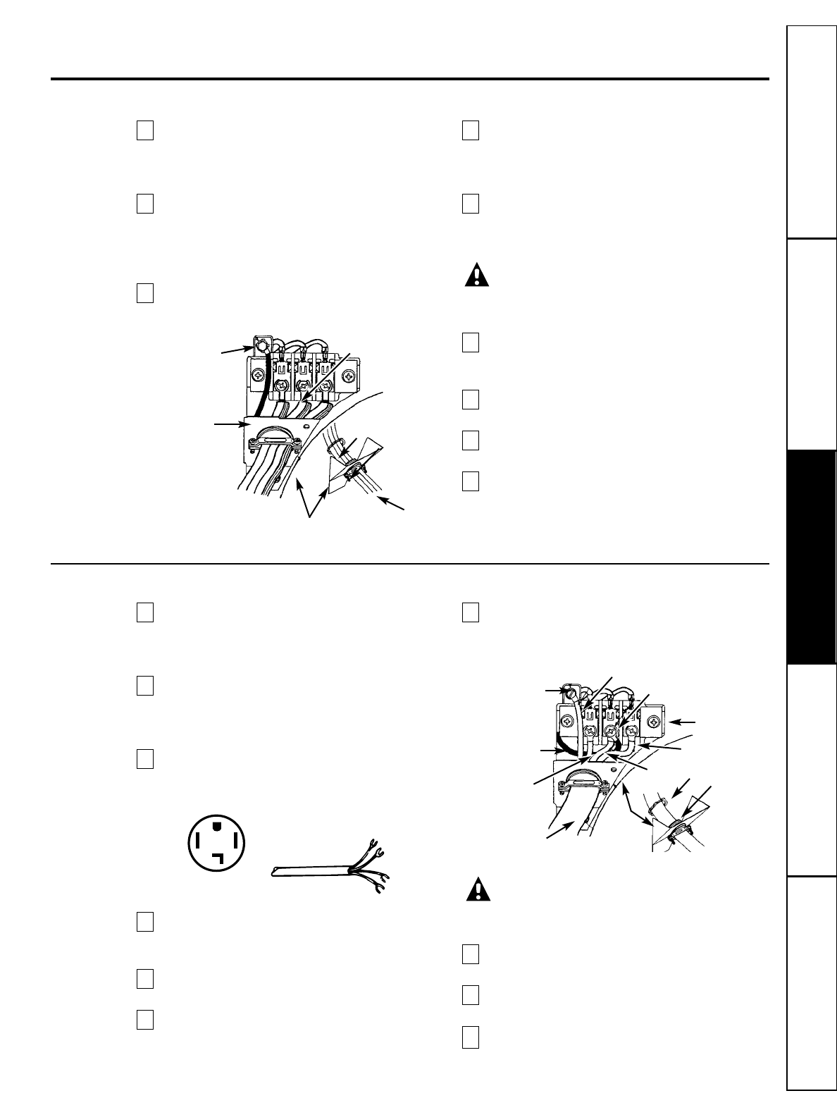
Attach the power cord neutral (center wire)
conductor to the silver-colored center terminal
on the terminal block. Tighten the screw
securely.
Attach the remaining two power cord outer
conductors to the outer brass-colored terminals
on the terminal block. Tighten both screws
securely.
WARNING: Do not make a sharp
bend or crimp wiring/conductor at
connections.
Reattach the strain relief mounting bracket to
the back of the dryer with two screws. Tighten
screws securely.
Tighten the fasteners securing the cord restraint
firmly against the power cord.
Tighten the strain relief nut securely so that the
strain relief does not turn.
Reinstall the terminal block access cover.
9
8
7
6
5
4
3
2
1
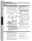
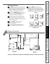
4-Wire System for Electric Dryers—MUST be used for Mobile Home Installations
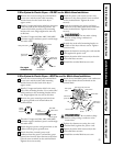
Remove the screws securing the terminal block
access cover and the strain relief mounting
bracket located on the back of the dryer
upper corner.
Install a UL-approved strain relief in the entry
hole of the mounting bracket. Use a strain relief
which attaches to the mounting bracket with a
nut. Finger-tighten the nut only at this time.
Remove the green neutral ground wire from
the green ground screw located above the
terminal block.
Thread a UL-approved 30A, 240V, 4 #10 AWG
minimum copper conductor power cord through
the strain relief.
Attach the green power cord ground wire to the
cabinet with the green ground screw.
Attach the white (neutral) power cord
conductor from the power cord and the green
ground wire from the dryer harness to the silver-
colored center terminal on the terminal block.
Tighten the screw securely.
Attach the red and black power cord conductors
to the outer brass-colored terminals on the
terminal block.
WARNING: Do not make a sharp
bend or crimp wiring/conductor at the
connections.
Tighten the fasteners securing the cord
restraint firmly against the power cord.
Tighten the strain relief nut securely so the
strain relief does not turn.
Reinstall the terminal block access cover.
10
9
8
7
6
5
4
3
2
1
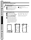
3-Wire System for Electric Dryers—DO NOT use for Mobile Home Installations
Green ground screw
Silver terminal
Nut
Tighten nut to
these threads
Power cord
Strain relief
mounting bracket
Green neutral
ground wire
Green ground
screw
Green neutral
ground wire
Red
White
Black
Terminal block
Silver terminal
Green power cord ground wire
Nut
Tighten nut to
these threads
Power cord
Strain
relief
mounting
bracket
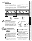
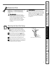
Typical 4
conductor
receptacle
Black 240V
White neutral
Red 240V
Green ground
Typical
4 conductor cord
15
Use copper
conductors only.
Consumer SupportTroubleshooting TipsOperating InstructionsSafety Instructions Installation Instructions