


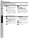
Replace brass connecting pipe that is not
plastic-coated. Stainless steel or plastic-coated
brass MUST be used.
WARNING: Never reuse old flexible
connectors. The use of old flexible connectors can
cause gas leaks and personal injury. Always use NEW
flexible connectors when installing a gas appliance.
Installation MUST conform with local codes, or
in the absence of local codes, with the National
Fuel Gas Code, ANSI Z223.1 (latest edition).
The gas supply line should be of 1/2″ (1.27 cm)
rigid pipe.
If codes allow, flexible metal tubing may be used
to connect your dryer to the gas supply line. The
tubing MUST be constructed of stainless steel or
plastic-coated brass.
The gas supply line MUST have an individual
shutoff valve.
A 1/8″ (0.32 cm) NPT minimum plugged
tapping, accessible for test gauge connection,
MUST be installed immediately upstream of the
gas supply connection to the dryer.
The dryer and its individual shutoff valve MUST
be disconnected from the gas supply piping
system during any pressure testing of the gas
supply piping system at test pressures in excess
of 1/2 psig (3.45 kPa).
The dryer MUST be isolated from the gas supply
piping system by closing its individual manual
shutoff valve during any pressure testing of the
gas supply piping system at test pressures
equal to or less than 1/2 psig (3.45 kPa).
7
6
5
4
3
2
1
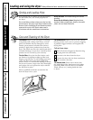
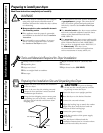
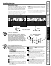
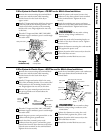
Exhaust Direction
All dryers are shipped set up for rear exhausting.
On electric dryers, exhausting can be on the cabinet
right or left side, or through the dryer bottom.
Gas dryers can exhaust on the cabinet right side or
the dryer bottom. To change exhaust direction you
will need Exhaust Kit, Pub No. 14-A018 and a rigid
metal 4″ 90 degree elbow. The kit is available through
your GE retailer. Follow the instructions supplied
with the kit.
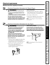
Gas Supply Requirements
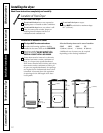
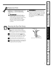
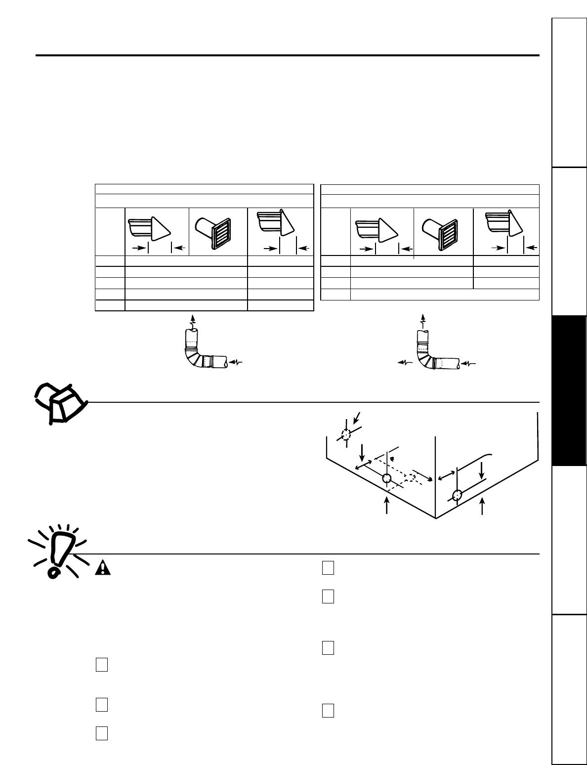
MAXIMUM LENGTH of 4“ (10.2 cm) Dia. RIGID METAL DUCT
PREFERRED VENT HOOD TYPE
0 60’ (18.28 m) 48’ (14.63 m)
1 52’ (15.84 m) 40’ (12.19 m)
2 44’ (13.41 m) 32’ (9.75 m)
3 32’ (9.75 m) 24’ (7.31 m)
4 28’ (8.53 m) 16’ (4.87 m)
Exhaust Ducting Length
The exhaust system should be inspected and cleaned
at least once a year with normal usage. The more the
dryer is used, the more often you should check the
exhaust system and vent hood for proper operation.
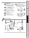
If roof vents or louvered plenums are used, they must
be equivalent to a 4″ dampered wall cap in regard to
resistance to airflow, prevention of back drafts and
maintenance required to prevent clogging.
• DO NOT assemble the duct work with fasteners that
extend into the duct. They will serve as collection
points for lint.
• Ductwork which runs through an unheated area or
is near an air conditioning duct should be insulated
to reduce condensation and lint buildup.
4” (10.2 cm) Louvered
4”
(10.2 cm)
Number of
90° turns
2.5”
(6.35
cm)
MAXIMUM LENGTH of 4“ (10.2 cm) Dia.
FLEXIBLE METAL DUCT
PREFERRED VENT HOOD TYPE
0 30’ (9.14 m) 18’ (5.49 m)
1 22’ (6.71 m) 14’ (4.27 m)
2 14’ (4.27 m) 10’ (3.05 m)
3 not recommended
4” (10.2 cm) Louvered
4”
(10.2 cm)
Number of
90° turns
2.5”
(6.35
cm)
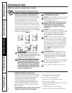
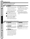
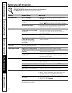
CORRECT
INCORRECT
INSTALL MALE FITTINGS IN
CORRECT DIRECTION
Same as
other side
EXHAUST DUCT LOCATING
DIMENSIONS
3-3/4″ (9.5 cm)
3-3/4″ (9.5 cm)
13-1/2″
(34 cm)
4-3/8″
(11 cm)
5-7/8″
(15 cm)
11
Consumer SupportTroubleshooting TipsOperating InstructionsSafety Instructions Installation Instructions
Installing the dryer.