


– 10 –
DETERGENT FEEDER (OPTIONAL BY OTHERS)
If installing a detergent feeder (by others), remove cap to expose
7
/8" diameter hole at rear of machine.
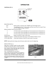
RINSE AGENT FEEDER (OPTIONAL BY OTHERS)
If a rinse agent feeder (by others) is being installed, remove the
1
/8" NPT pipe plug to access the tapped
hole in the incoming water line below the vacuum breaker on top of the machine.
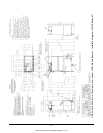
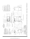
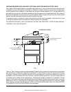
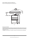
VENT EXIT
A vent exit (7" x 11" x 10") is provided in the top of the machine to allow for expansion of air. It should not
be directly connected to an external vent.
VENT FAN CONTROL (OPTIONAL); POWER VENT (OPTIONAL)
The Vent Fan Control option (factory- or fi eld-installed) provides switching for a vent fan (by others). The
vent hood comes on when the UW50 is on and goes off when the UW50 is off. This is appropriate for
a hood over a UW50 with gas tank heat. The Vent Fan Control can be rewired by your Hobart service
technician to control the Power Vent option (not available on UW50 with gas tank heat). Power Vent is
used on UW50 with steam or electric tank heat to exhaust moist air from the chamber after the rinse cycle
is fi nished. Power Vent operates for 45 seconds. Power Vent (fi eld installed only) extends upward 13
1
/8"
above the Vent Exit (22
7
/8" above the top of the wash chamber) and terminates in a round duct connection
for a 10
1
/4" O.D. duct.
ELECTRICAL CONNECTION
Electrical and grounding connection must comply with the applicable portions of
the National Electrical Code and/or other local electrical codes.
Disconnect electrical power supply and follow lockout / tagout procedures.
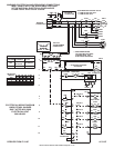
Connect incoming power to the control box in accordance with the wiring diagram located inside the control
box and the electrical data chart. The front trim rail and the front panel must be removed to access the
control box.
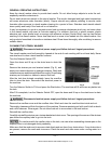
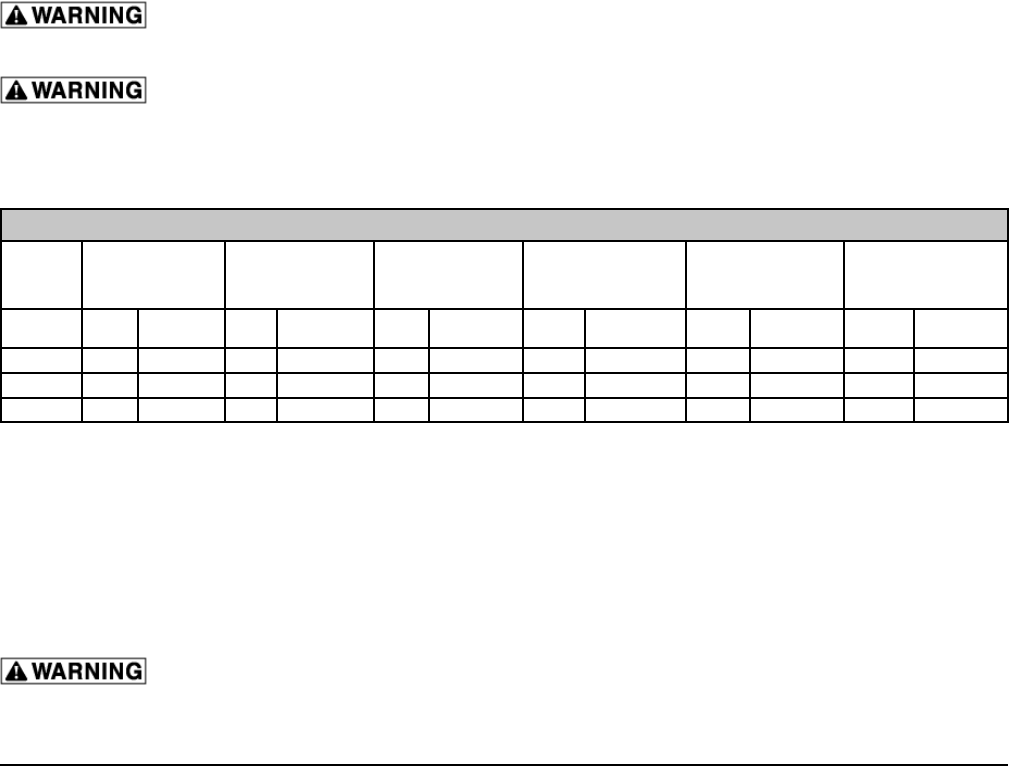
ELECTRICAL DATA
10KW Electric
Heat (Single Point
Connections)
10KW Electric Heat
With 14KW Electric
Booster (Single Point
Connections)
Steam Tank Heat
(Injector or Coil)
(Single Point
Connections)
Steam Tank Heat (Injector
or Coil) With 14KW
Electric Booster (Single
Point Connections)
Gas Tank Heat (Single
Point Connections)
Gas Tank Heat With 14KW
Electric Booster (Single
Point Connections)
Volts/Hz/Ph Rated
Amps
Circuit Size*
(Amps)
Rated
Amps
Circuit Size*
(Amps)
Rated
Amps
Circuit Size*
(Amps)
Rated
Amps
Circuit Size*
(Amps)
Rated
Amps
Circuit Size*
(Amps)
Rated
Amps
Circuit Size*
(Amps)
208/60/3 50.3 70 89.2 **100 20.3 25 60.3 80 21.4 30 60.3 80
240/60/3 46.2 60 79.9 **100 17.6 25 52.3 70 18.6 25 52.3 70
480/60/3 23.5 30 40.4 50 9.2 15 26.4 35 9.6 15 26.4 35
* Minimum Circuit Size / Maximum Protective Device (Amps) compiled in accordance with the National Electrical Code (NFPA 70), latest edition.
** For supply connection, use wires suitable for at least 90°F or equivalent.
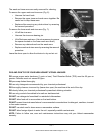
Rotation of Pump Motor
Before using the machine, check the pump motor rotation to be sure it is rotating in the right direction. From
the front of the machine, the motor should rotate counterclockwise. Looking from the rear of the machine,
the correct rotation is clockwise. Inspection is easiest from the right side using a fl ashlight and mirror to
check the motor fan in front. Be aware that the mirror will reverse the perceived direction.
If the pump motor is rotating in the wrong direction, follow this procedure.
Disconnect electrical power supply and follow lockout / tagout procedures.
Reverse any two of the three incoming line wires (not the ground wire). Reconnect and recheck rotation
of pump motor.
UW50 Untensil Washer 208-240/60/3 Page 21 of 112