


– 7 –
PLUMBING CONNECTIONS
Plumbing connections must comply with applicable sanitary, safety and plumbing
codes.
Water Supply Connection
Water must be proper hardness. Recommended water hardness is 1 grain or less. Higher hardness may
cause excessive formation of lime scale. Chlorides must not exceed 50 ppm.
A water hammer arrestor (meeting ASSE-1010 Standard) should be provided (by others) in the water
supply line ahead of its connection to the line strainer. The water supply line should be a
3
/4" pipe.
A fl owing pressure of 15 to 25 psig is required at the pressure gauge, provided. The pressure gauge may
be connected to a petcock, if equipped, and should remain closed, except when the fl owing pressure
is being checked. If the fl owing pressure exceeds 25 psig, a pressure-reducing valve (not supplied on
machines without booster) must be installed in the water supply line. A pressure-reducing valve with relief
bypass is furnished with machines equipped with a 14KW electric booster.
The water-pressure regulator must have a relief bypass. Failure to use the proper type of
pressure regulator may result in damage to the unit.
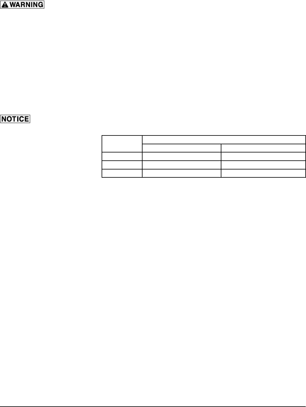
The minimum water supply
temperature per cycle time
required to maintain 180°F fi nal
rinse temperature is shown at
the right:
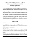
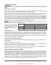
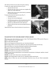
Drain Connection
A proper drain should be connected to the 2" internal threads at the "T" fi tting underneath the machine.
The drain can be connected on either the left or right side of the "T" fi tting. The right side of the "T" fi tting
is plugged at the factory, allowing the drain to be connected on the left side. If it is more convenient to
connect the drain on the right side, remove the plug from the right side of the "T" fi tting, reinstall it on the
left side and connect the drain to the right side.
GAS CONNECTION (WHEN SPECIFIED)
Check the gas data plate attached to the dishwasher or tag attached to the gas burner tubing for type of
gas to be used.
Connect the gas supply to the machine.
The burner is not adjustable. If line pressure is above 7" W.C. (natural gas) or 11" W.C. (propane gas), an
additional regulator valve (not supplied) must be installed in the supply line.
The burner is ignited by solid state electronic circuitry; there is no pilot light. Gas fl ow is regulated by the
temperature control circuit via a blower and centrifugal switch system.
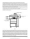
STEAM CONNECTION (WHEN SPECIFIED)
Machines equipped with steam injector tank heat have a steam connection (
3
/4" female pipe thread) located
under the machine at the rear, 6" above the fl oor. Machines equipped with steam coil tank heat have the
steam supply connection (
3
/4" female pipe thread) located at the rear of the wash tank, 19" above the fl oor,
and a condensate return connection (
3
/4" female pipe thread), located at the rear of the wash tank, 12
3
/8"
above the fl oor (a bucket-type trap is furnished). For either type of steam heat, fl owing steam pressure
should be 15 to 25 psig (50 psig maximum). A manually operated steam control valve (supplied by others)
should be installed at a convenient location ahead of the steam supply connection.
Cycle
Minimum Water Supply Temperatures
With Optional Booster Heater Without Booster Heater
2 Minute 140°F 180°F
4 Minute 110°F 180°F
6 Minute 80°F 180°F
UW50 Untensil Washer 208-240/60/3 Page 18 of 112