


Repair
309518P 27
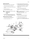
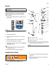
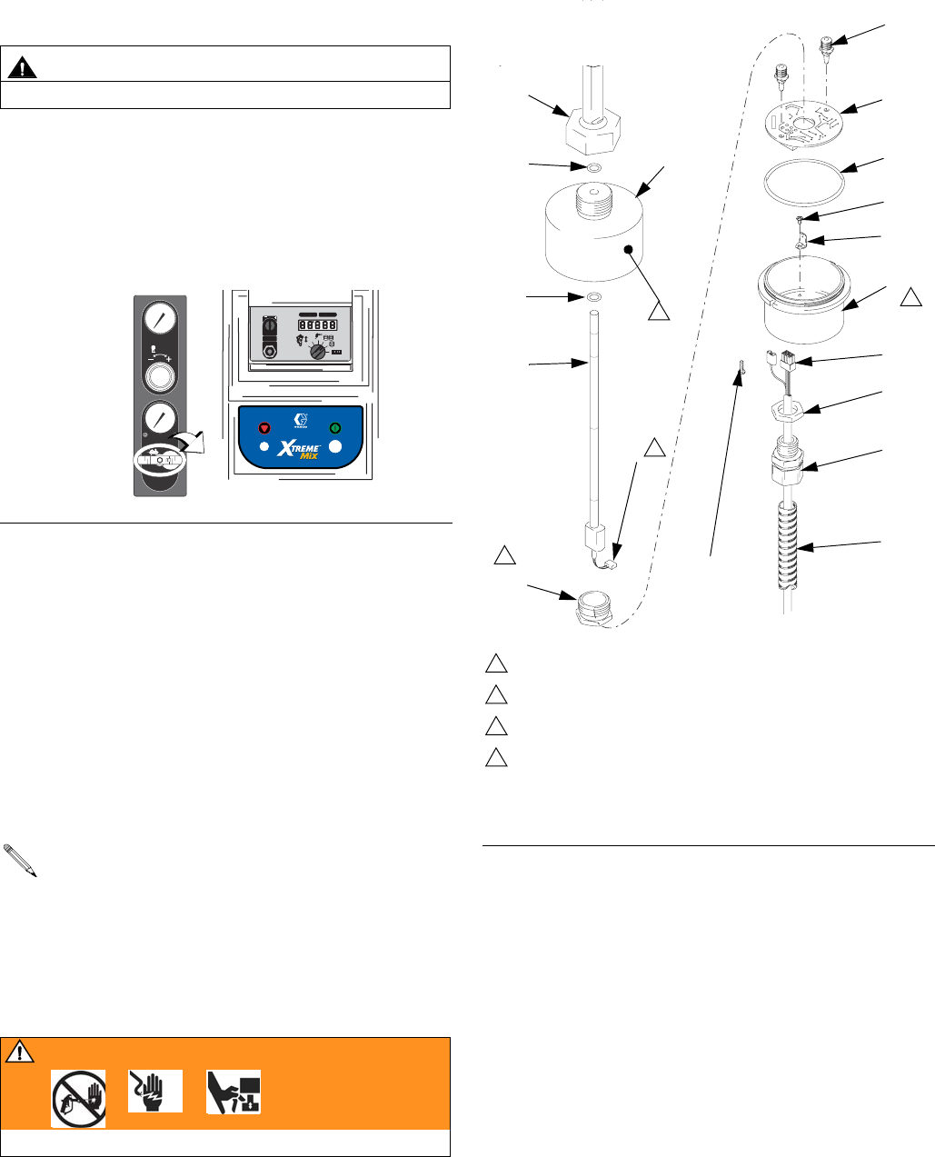
Sensor
Reference numbers with * are included in repair kit
246345. Reference numbers with † are included in
repair kit 246344.
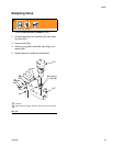
1. Close main air shutoff valve on air supply line and
unit. F
IG. 22.
2. Unscrew sensor cap (701†) from nut (712†). F
IG.
23.
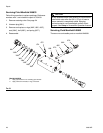
3. Disconnect cable (705*).
4. Unscrew fitting (713*), locknut (719*), and cover
(702*).
5. Disconnect sensor cable (Y) from board (703†).
6. Remove and replace parts as needed.
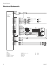
7. Reassemble and mount sensor. Refer to Electrical
Schematic, page 28.
8. Recalibrate main circuit board. See page 19.
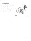
Displacement Pump
1. Follow Pressure Relief Procedure, page 7.
2. Disconnect 90° swivel (30) from pump lower. Refer
to page 32.
3. Remove pump lower and service as instructed in
pump manual 311762.
CAUTION
To avoid damaging board, wear a grounding strap.
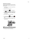
F
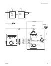
IG. 22
Mount sensor as close to magnet as possible
without touching it.
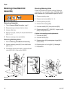
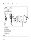
I
O
SUPPLY AIR
PRESSURE
PUMP AIR
PRESSURE
VALVE
BA
VALVE
B
A
DATA PORT
SETUP KEY
0
PLURAL COMPONENT PROPORTIONER
I
O
PSI
Bar
MPa
PSI
Bar
MPa
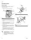
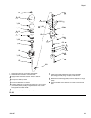
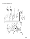
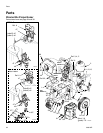
FIG. 23
704†
703†
720†
710*
709*
702*
719*
713*
711*
†714
701†
†707
†706
†708
†712
721*
Torque to 60 in-lbs (7 N•m).
Plug connector into connector on board (703).
Calibration value location.
Before assembling cover (702*) to cap (701
†), assemble cable
(705*) through fitting (713*) and cover (702*), and plug cable into
connector on board (703
†) and to ground lug.
1
2
3
4
1
2
3
705*
Y
4
WARNING
Read warnings, page 5.