


– 22 –
Testing the Inverter
Fuse
Signal (Beeper)
The beeper is mounted on the inverter, but
controlled by the main control board.
• The beeper uses the same 12 VDC supply as
the LCD backlight.
• To check the 12 VDC circuit, measure
between pin 3 (white wire) on white connector
CN11 and pin 8 (pink wire) on the blue
connector CN14. (See
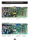
Inverter and Main board
Pin Connectors.
)
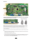
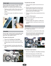
• The inverter receives 120 VAC at the red 3-pin
connector CN10. The voltage first passes
through an RF choke. The RF choke filters the
line voltage and is replaced as an assembly. If
120 VAC is not present, check the wall outlet,
power cord, and RF choke.
• When 120 VAC is present at CN10, there
should be 5 VDC between pin 3 (white wire)
and pin 7 (blue wire) on the white connector
CN11. (This voltage is used to keep the
membrane and LCD display in standby,
waiting for a key-press.)
• Upon activating a membrane pad or touching
the LCD screen, the control "wakes up" and a
second transformer is energized. When this
condition is present, 12 VDC and 20 VDC can
be measured on the board.
• 12 VDC should be between pin 3 (white wire)
on white connector CN11 and pin 8 (pink wire)
on the blue connector CN14.
• 20 VDC should be between pin 3 (white wire)
on white connector CN11 and pin 12 (brown
wire) on the blue connector CN14.
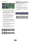
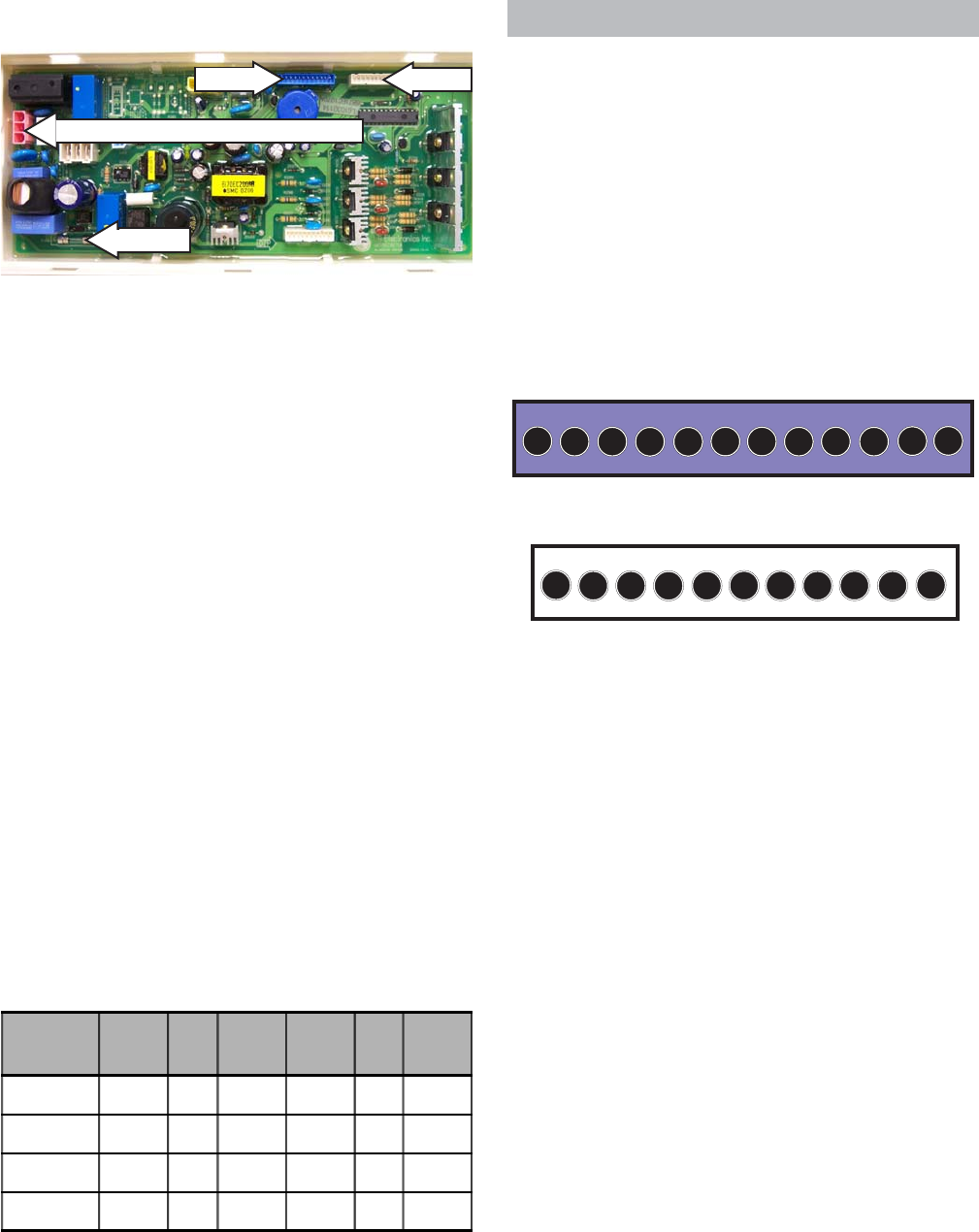
CN14
12 11
109876
54321
CN14
CN11
CN11
1110987654321
120 VAC Input From RF Choke CN10
Voltage CON Pin
Wire
Color
CON Pin
Wire
Colo
r
120 VAC CN10 1 BLK CN10 3 WHT
5 VDC CN11 3 WHT CN11 7 BLU
12 VDC CN11 3 WHT CN14 8 PNK
20 VDC CN11 3 WHT CN14 12 BRN