


494 Fabric OS Administrator’s Guide
53-1001763-02
FC-FC Routing and Virtual Fabrics
21
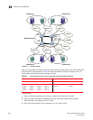
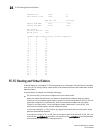
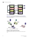
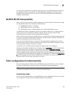
FIGURE 76 EX_Ports in a base switch
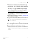
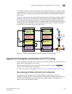
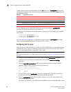
Figure 77 shows a logical representation of the physical chassis and devices in Figure 76. As
shown in Figure 77, Fabric 128 and Fabric 15 are edge fabrics connected to a backbone fabric.
Fabric 1 is not connected to the backbone, so the device in Fabric 1 cannot communicate with any
of the devices in the other fabrics.
FIGURE 77 Logical representation of EX_Ports in a base switch
Backbone-to-edge routing with Virtual Fabrics
Since the base switch does not allow F_Ports, you cannot have devices connected to the base
switch.
Logical switch 8
(Base switch)
Fabric ID 8
Logical switch 7
Fabric ID 15
Logical switch 6
Fabric ID 1
Allows XISL use
Logical switch 5
(Default logical switch)
Fabric ID 128
Physical chassis 2
Logical switch 4
(Base switch)
Fabric ID 8
E
Logical switch 3
Fabric ID 15
E
Logical switch 2
Fabric ID 1
Allows XISL use
E
Logical switch 1
(Default logical switch)
Fabric ID 128
E
Physical chassis 1
E
E
E
XISL
EX
EX
F
F
E
IFL
IFL
ISL
ISL
Logical ISL
F
Backbone fabric
Fabric 8
Edge fabric
Fabric 15
SW7
Edge fabric
Fabric 128
SW5
Fabric 1
SW6
SW2
SW8
SW1
SW4
SW3
E
EX
EX
E