


Fabric OS Administrator’s Guide 235
53-1001763-02
Creating a logical fabric using XISLs
10
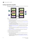
For the example shown in Figure 31, you would create a logical switch with FID 1 and a
logical switch with FID 15.
c. Assign ports to the logical switch, as described in “Adding and removing ports on a logical
switch” on page 229.
d. Physically connect devices and ISLs to these ports on the logical switch.
e. (Optional) Configure the logical switch to use XISLs, if it is not already XISL-capable. See
“Configuring a logical switch to use XISLs” on page 232 for instructions.
By default, newly created logical switches are configured to allow XISL use.
f. Repeat step a through step e in all chassis that are to participate in the logical fabric,
using the same fabric ID whenever two switches need to be part of a single logical fabric.
5. Enable all logical switches by entering the following command on each logical switch that you
created in step 4 (the base switches are already enabled):
switchenable
The logical fabric is formed.
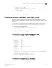
The fabricShow command displays all logical switches configured with the same fabric ID as
the local switch and all non-Virtual Fabric switches connected through ISLs to these logical
switches.
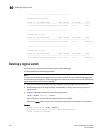
The switchShow command displays logical ports as E_Ports, with -1 for the slot and the user
port number for the slot port.