


280 Fabric OS Administrator’s Guide
53-1001763-02
Virtual Fabric considerations for Traffic Isolation Zoning
12
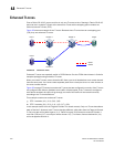
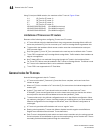
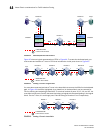
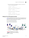
FIGURE 44 Dedicated path with Virtual Fabrics
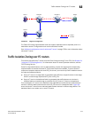
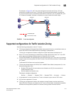
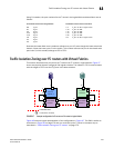
Figure 45 shows a logical representation of FID1 in Figure 44. To create the dedicated path, you
must create and activate a TI zone in FID1 that includes the circled ports shown in Figure 45.
FIGURE 45 Creating a TI zone in a logical fabric
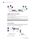
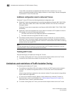
You must also create and activate a TI zone in the base fabric to reserve the XISLs for the dedicated
path. In Figure 44, the XISLs highlighted (by a dotted line) in the base fabric can be reserved for
FID1 by defining and activating a base fabric TI zone that consists of ports 10, 12, 14, and 16. You
must also include ports 3 and 8, because they belong to logical switches participating in the logical
fabric. For the TI zone, it is as though ports 3 and 8 belong to Domains 1 and 2 respectively.
FIGURE 46 Creating a TI zone in a base fabric
= Dedicated Path
Chassis 1 Chassis 2
XISL
XISL
XISL
XISL
Domain 8
Domain 7
Base switch
Domain 2
LS2, FID3
Domain 6
LS1, FID1
Domain 5
Base switch
Domain 1
LS4, FID3
Domain 4
LS3, FID1
Domain 3
Domain 9
2
4
= Ports in the TI zones
6
7
12
1
8
5
3
8
1715
16
14
1311
10
9
Host
Target
= Dedicated Path
2
4
= Ports in the TI zones
6
7
5
17
16
11
10
8
1
3
8
9
Host
Domain 8 Domain 3 Domain 5 Domain 9
Target
= Dedicated Path
= Ports in the TI zones
4
17
15
13
12
11
10
3
8
Domain 1 Domain 7 Domain 2
14
16
7