


24
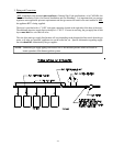
Consistent gas pressure is essential at ALL gas connections. It is recommended that a 1-inch pipe gas loop
be installed in the supply line serving a bank of dryers. An in-line pressure regulator must be installed in the
gas supply line (header) if the (natural) gas pressure exceeds 12.0 inches of water column (W.C.) pressure.
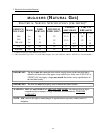
NOTE: A water column test pressure of 3.5 inches for natural gas dryers is required at the gas valve
pressure tap of each dryer for proper and safe operation.
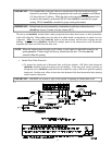
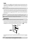
A 1/8" N.P.T. plugged tap, accessible for a test gauge connection, must be installed in the main gas supply
line immediately upstream of each dryer.
IMPORTANT: Pipe joint compounds that resist the action of natural gas must be used.
IMPORTANT: Test ALL connections for leaks by brushing on a soapy water solution (liquid
detergent works well).
WARNING: NEVER TEST FOR LEAKS WITH A FLAME!!!
ALL components and materials must conform to National Gas Code specifications, or in CANADA, the
Canadian Installation Codes CAN/CGA-B149.1-M91 (Natural Gas) or CAN/CGA-B149.2-M91 (L.P. Gas)
or LATEST EDITION. It is important that gas pressure regulators meet applicable pressure requirements
and that gas meters be rated for the total amount of ALL the appliance BTU's being supplied.
IMPORTANT: The dryer and its individual shut-off valve must be disconnected from the gas supply
piping system during any pressure testing of that system at test pressures in excess of
1/2 psig (3.5 kPa).
NOTE: The dryer must be isolated from the gas supply piping system by closing its individual manual
shut-off valve during any pressure test of the gas supply system at test pressures equal to or less
than 1/2 psig (3.5 kPa).
H. PREPARATION FOR OPERATION AND START-UP
The following items should be checked before attempting to operate the dryer:
1. Read ALL "CAUTION," "WARNING," and "DIRECTION" labels attached to the dryer.
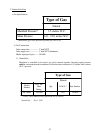
2. Check incoming supply voltage to be sure that it is the same as indicated on the dryer data label affixed to the
back side of the top front control and service door. In the case of 208 VAC or 230/240 VAC, THE SUPPLY
VOLTAGE MUST MATCH THE ELECTRIC SERVICE EXACTLY.
3. Check to assure that the dryer is connected to the type of heat or gas indicated on the dryer data label.
4. The sail switch damper assembly was installed and adjusted at the factory prior to shipping. However, each
sail switch adjustment must be checked to assure that this important safety control is functioning.
5. Be sure that ALL gas shut-off valves are in the open position.
6. Be sure ALL side and base panels are on the dryer.