


113226-6 www.amdry.com 27
7. Check that ALL back guard panels and service box covers have been replaced.
8. Check the lint drawer to ensure that it is closed and secured in place.
9. Rotate the basket (tumbler/drum) by hand to be sure it moves freely.
10. STEAM MODELS – Check to ensure that a clean, dry, and regulated air supply (80 psi [5.51 bar]) is on
the dryer (with air operated damper system only).
11. STEAM MODELS – Check to ensure
ALL steam shutoff valves are open.
12. STEAM MODELS – Check steam damper operation.
13. Check basket (tumbler) bearing setscrews to ensure that they are
ALL tight.
14. Check vent is connected to the dryer and is exhausted to the outdoors.
15. There should be a source of fresh air entering the room. This source should not be near where the
dryers exhaust to the outside.
J. PREOPERATIONAL TEST
ALL dryers are thoroughly tested and inspected before leaving the factory. However, a preoperational test
should be performed before the dryer is publicly used. It is possible that adjustments have changed in transit or
due to marginal location (installation) conditions.
1. Turn on electric power to the dryer.
2. Refer to the Operating Instructions for starting your particular model dryer.
3. GAS MODELS ONLY
a. When a gas dryer is first started (during initial start-up), it has a tendency not to ignite on the first ignition
attempt. This is because the gas supply piping is filled with air, so it may take a few minutes for the air
to be purged from the lines.
NOTE: During the purging period, check to be sure that ALL gas shutoff valves are open.
NOTE: Gas dryers are equipped with a Direct Spark Ignition (DSI) system, which has internal
diagnostics. If ignition is not established within three (3) times, the heat circuit in the DSI
module will “LOCK OUT” until it is manually reset. To reset the DSI system, open and close
the main door and restart the dryer.
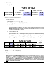
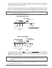
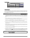
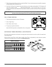
b. A gas pressure test should be taken at the gas valve pressure tap of each dryer to ensure that the
water column (W.C.) pressure is correct and consistent.
NOTE: Water column pressure requirements (measured at the pressure tap of the gas valve body):
Natural Gas -------------------- 3.5 Inches (8.7 mb) Water Column.
Liquid Propane (L.P.) Gas --- 10.5 Inches (26.1 mb) Water Column.