


92
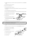
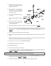
10) Secure the gear reducer to the drive shaft by reinstalling the three (3) bolts into the taper lock
bushing and tighten evenly for proper mounting.
11) Repeat Step #12 to reinstall the other taper lock bushing.
12) Reinstall the bolt into the turnbuckle and mounting bracket.
13) Reinstall V-belts and tighten turnbuckle.
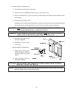
14) Prior to operating new gear (speed) reducer, fill with 1.48 quarts (1.4 liters) of SAE 90 gear oil.
IMPORTANT: DO NOT OVERTIGHTEN TURNBUCKLE.
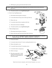
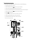
15) Mount the pillow block bearings onto the mounting pads (using the bolts that were removed)...DO
NOT tighten.
16) Tighten the taper lock bushing into the drive wheels.
17) Tighten the adjustment bolts until the basket (tumbler) is centered.
IMPORTANT: Remove the wooden blocks that were inserted under the basket (tumbler).
18) Tighten the bolts on the pillow block bearings.
NOTE: Verify correct mounting position of the gear reducer. Make the necessary corrections and/or
adjustments to the gear reducer for proper mounting. Changing the drain plug, breather plug,
as well as the turnbuckle mounting pad may be required.
NOTE: Inspect ALL of the work performed checking for security of parts and proper alignment.
19) Reestablish electrical power to the dryer.
3. Retaining Wheel Components
a. Retaining Wheel Cover Panel Removal
1) Discontinue electrical power to the dryer.
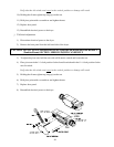
2) Remove the top front panel to access the two (2) front retaining wheels and/or the rear top panel to
access the two (2) rear retaining wheels.
3) To gain access to the bottom front retaining wheel the bottom panel must be removed. (The bolts
securing this panel are located behind the right and left control panels.)
NOTE: The lower front retaining wheel does not have a cover.
NOTE: The guard panel must be removed from the dryer to access the rear bottom panel.
4) Remove the bolts from the guard panel to gain access to the rear bottom retaining wheel.