


26 American Dryer Corp. 113335-12
Manual Reset
Burner Hi-Limit Instructions _________
Phase 7
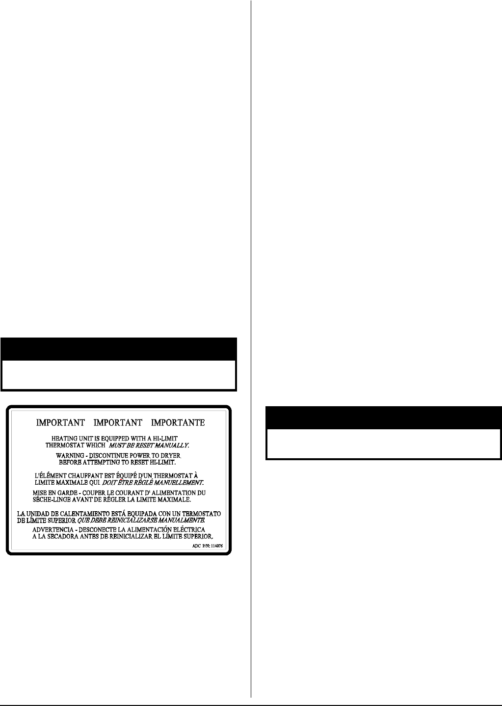
This dryer was manufactured with a manual reset burner
hi-limit thermostat, which is monitored by the Phase 7
computer. If the burner hi-limit is open prior to the start of
the drying cycle, the dryer will start momentarily and then
shut down, the Phase 7 computer will display “BURNER HIGH
LIMIT FAULT” with an audio indication.
If the burner hi-limit opens during a drying cycle, the Phase 7
computer will also display the same error code described
above, along with an audio indication. If the drum temperature
is above 100° F (38° C), the dryer will continue to run with no
heat for 3 minutes or until the drum temperature has dropped
below 100° F (38° C). The clear/stop button on the Phase 7
keypad must be pressed to clear the error condition.
Dual Timer
This dryer was manufactured with a manual reset burner
hi-limit thermostat. If the burner hi-limit is open prior to the
start of the drying cycle, or during the cycle, the dryer will not
recognize the open state of the burner hi-limit and will start
or continue through the drying cycle with no heat. Manual
reset hi-limit must be reset manually.
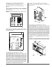
This hi-temperature condition may be caused due to a
restricted exhaust, poor airflow, or improper burner operation.
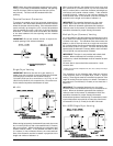
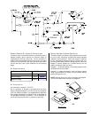
The location of the burner hi-limit is on the right side of the
burner box, looking at the burner from the front of the dryer.
Discontinue power to dryer before attempting to
reset hi-limit.
▲ WARNING
!
Fire Suppression System _____________
Before You Start,
Check Local Codes and Permits
Call your local water company or the proper municipal
authority for information regarding local codes.
IMPORTANT: It is your responsibility to have all plumbing
connections made by a qualified professional to ensure
that the plumbing installation is adequate and conforms to
local, state, and federal regulations or codes.
It is the installer’s or owner’s responsibility to see that the
necessary or required water, water pressure, pipe size, or
connections are provided. The manufacturer assumes no
responsibility if the F.S.S. is not connected, installed, or
maintained properly.
Installation
Requirements
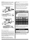
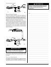
The connection point to the electric water solenoid valve is a
3/4-11.5 NH, the F.S.S. must be supplied with a minimum
water pipe size of 1/2” and be provided with 40 psi +/- 20 psi
(2.75 bar +/- 1.37 bar) of pressure. For use of optional manual
bypass, a second source with the same piping and pressure
requirements is required.
Flexible 1/2 feeds must be provided to avoid damage to
electric water solenoid valve by vibration.
IMPORTANT: Flexible supply line/coupling must be used.
Solenoid valve failure due to hard plumbing connections
will void warranty.
If the rear area of the dryer, or the water supply is located in
an area where it will be exposed to cold/freezing
temperatures, provisions must be made to protect these water
lines from freezing.
If the water in the supply line or water solenoid
valve freezes, the F.S.S. will be inoperative!!
▲ WARNING
!
IMPORTANT: Appliance is to be connected to the water
mains using a new hose set and the old hose set should
not be reused.
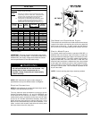
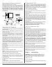
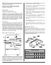
Water Connection
The water connection is made to the 3/4-11.5 NH bushing
located at the rear upper right area of the dryer. Flexible
supply line/coupling must be used in effort to avoid damage
to electric water solenoid valve.
IMPORTANT: Flexible supply line/coupling must be used.
Solenoid valve failure due to hard plumbing connections
will void warranty. It is recommended that a filter or
strainer be installed in the water supply line.