


20 American Dryer Corp. 113335-12
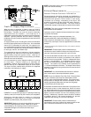
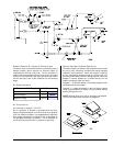
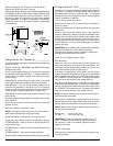
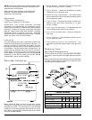
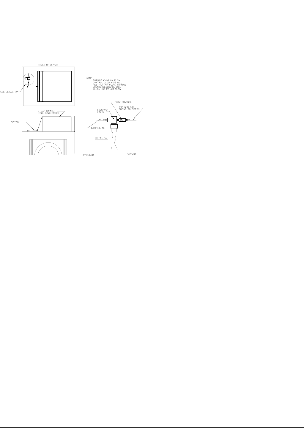
Steam Damper Air Piston (Flow Control)
Operation Adjustment System
Although the damper operation was tested and adjusted prior
to shipping at 80 psi (5.51 bar), steam damper operation must
be checked before the dryer is put into operation. Refer to
the previous page for instructions to check steam damper
system operation. If damper air adjustment is necessary,
locate flow control valve and make necessary adjustments
as noted below.
Preparation for Operation ____________
The following items should be checked before attempting to
operate the dryer:
Read all “CAUTION,” “WARNING,” and “DIRECTION” labels
attached to the dryer.
Check incoming supply voltage to be sure that it is the same
as indicated on the dryer data label. In case of 208 VAC or
230/240 VAC, the supply voltage must match the electric
service exactly.
GAS MODELS – check to ensure that the dryer is connected
to the type of heat/gas indicated on the dryer data label.
GAS MODELS – the sail switch damper assembly was
installed and adjusted at the factory prior to shipping.
However, each sail switch adjustment must be checked to
ensure that this important safety control is functioning.
GAS MODELS – be sure that all gas shutoff valves are in the
open position.
Be sure all back panels (guards) and electric box covers have
been replaced.
Check all service doors to ensure that they are closed and
secured in place.
Be sure lint drawer is securely in place.
NOTE: Lint drawer must be all the way in place to activate
safety switch otherwise the dryer will not start.
Rotate the tumbler by hand to be sure it moves freely.
Check bolts, nuts, screws, terminals, and fittings for security.
STEAM MODELS – check to ensure air supply (80 psi [5.51
bar]) is on the dryer.
STEAM MODELS – check to ensure all steam shutoff valves
are open.
STEAM MODELS – check steam damper operation.
Check tumbler bearing setscrews to ensure they are all tight.
Preoperational Test __________________
All dryers are thoroughly tested and inspected before leaving
the factory. However, a preoperational test should be
performed before the dryer is publicly used. It is possible
that adjustments have changed in transit or due to marginal
location (installation) conditions.
Turn on electric power to the dryer.
Make sure the main door is closed and the lint drawer is
securely in place.
Refer to the Operating Instructions for starting your particular
model dryer.
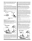
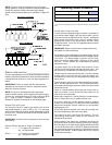
Check to ensure that the tumbler starts in the clockwise
direction. Additionally, check the direction of the blower motor
(impellor/fan) to ensure that the blower motor (impellor/fan)
rotates in the clockwise direction as viewed from the front. If
it is, the phasing is correct. If the phasing is incorrect, reverse
2 of the leads at L1, L2, or L3, of the power supply connections
made to the dryer.
IMPORTANT: Dryer blower motor (impellor/fan) as viewed
from the front must turn in the clockwise direction,
otherwise dryer efficiency will be drastically reduced and
premature component failure can result.
Heat Circuit Operational Test
Gas Models
When the dryer is first started (during initial start-up), the
burner has a tendency not to ignite on the first attempt. This
is because the gas supply piping is filled with air, so it may
take a few minutes for this air to be purged.
If the dryer is equipped with a DSI system, the DSI control
module has internal diagnostics. If ignition is not established
within 3 attempts, the heat circuit in the DSI control module
will “LOCKOUT” until manually reset. To reset the DSI system,
open and close the main door and restart the dryer.
If the dryer is equipped with an HSI system, the HSI control
module has internal diagnostics. If ignition is not established
after the first attempt, the heat circuit in the HSI control module
will “LOCKOUT” until manually reset. To reset the HSI system,
open and close the main door and restart the dryer.
NOTE: During the purging period, check to be sure that all
gas shutoff valves are open.
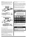
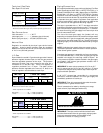
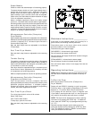
Once ignition is established, a gas pressure test should be
taken at the gas valve pressure tap of each dryer to ensure
that the water column pressure is correct and consistent.
NOTE: Water column pressure requirements (measured at
the gas valve pressure tap)...
Natural Gas........ 3.5 in wc (8.7 mb).
L.P. Gas ............. 10.5 in wc (26.1 mb).
IMPORTANT: There is no regulator provided in an L.P.
dryer. The water column pressure must be regulated at
the source (L.P. tank) or an external regulator must be
added to each dryer.
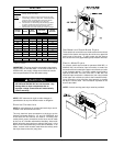
Electric Models
Check the oven contactor(s) to ensure that the electric oven
is cycling properly.