


113335-12 www.amdry.com 13
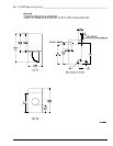
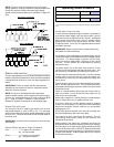
NOTE: When the exhaust ductwork passes through a wall,
ceiling, or roof made of combustible materials, the opening
must be 2-inches (5.08 cm) larger than the duct (all the
way around). The duct must be centered within this
opening.
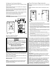
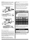
Outside Ductwork Protection
To protect the outside end of the horizontal ductwork from
the weather, a 90° elbow bent downward should be installed
where the exhaust exits the building. If the exhaust ductwork
travels vertically up through the roof, it should be protected
from the weather by using a 180° turn to point the opening
downward. In either case, allow at least twice the diameter
of the duct between the duct opening and the nearest
obstruction.
IMPORTANT: Do not use screens, louvers, or caps on the
outside opening of the exhaust ductwork.
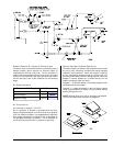
Single Dryer Venting
IMPORTANT: Minimum duct size for a gas, electric, or
steam dryer with a vertical run and not more than 3 elbows
(including dryer connection and outside outlets) is
16-inches (40.64 cm) for a round duct or 14-1/2” by 14-1/2”
(36.83 cm by 36.83 cm) for a square duct. Duct size must
not be reduced anywhere downstream of dryer.
ML-130
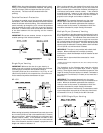
When venting horizontally, the ductwork from each dryer must
be 14-inches (35.56 cm) and not exceed 20 feet (6.1 meters)
with no more than 1 elbow (including dryer connections and
outside exhaust outlets). If the ductwork exceeds 20 feet
(6.1 meters) or has numerous elbows, the cross-sectional
area of the ductwork must be increased in proportion to the
length and number of elbows in it.
When venting vertically, the ductwork from each dryer must
be a minimum of 16-inches (40.64 cm) and not exceed 20
feet (6.1 meters) with no more than 3 elbows (including dryer
connections and outside exhaust outlets). If the ductwork
exceeds 20 feet (6.1 meters) or has numerous elbows, the
cross-sectional area of the ductwork must be increased in
proportion to the length and number of elbows in it.
IMPORTANT: For extended ductwork runs, the cross
section area of the duct can only be increased to an
extent. When the ductwork approaches the maximum
limits as noted in this manual, a professional HVAC firm
should be consulted for proper venting information.
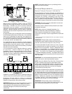
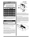
Multiple Dryer (Common) Venting
If it is not feasible to provide separate exhaust ducts for each
dryer, ducts from individual dryers may be channeled into a
“common main duct.” The individual ducts should enter the
bottom or side of the main duct at an angle not more than
45° in the direction of airflow and should be spaced at least
48-3/8 inches (122.87 cm) apart. The main duct should be
tapered, with the diameter increasing before each individual
14-inch (35.56 cm) minimum duct is added.
IMPORTANT: The dryer is not provided with a back draft
damper. When exhausted into a multiple (common)
exhaust line, a back draft damper must be installed at each
dryer duct.*
No more than 4 dryers should be connected to 1 main
common duct.
* Models manufactured as of September 24, 2001, have a damper in the dryer
as a standard item.
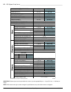
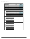
The illustrations on the following page show the minimum
cross-sectional area for multiple dryer round or square
venting. These figures must be increased in proportion if the
length of ducting from the last dryer to where it exhausts to
the outdoors is over 20 feet (6.1 meters) or has more than 1
elbow in it.
IMPORTANT: For extended ductwork runs, the cross-
sectional area of the ductwork can only be increased to an
extent. When the ductwork approaches the maximum
limits as noted in this manual, a professional HVAC firm
should be consulted for proper venting information.
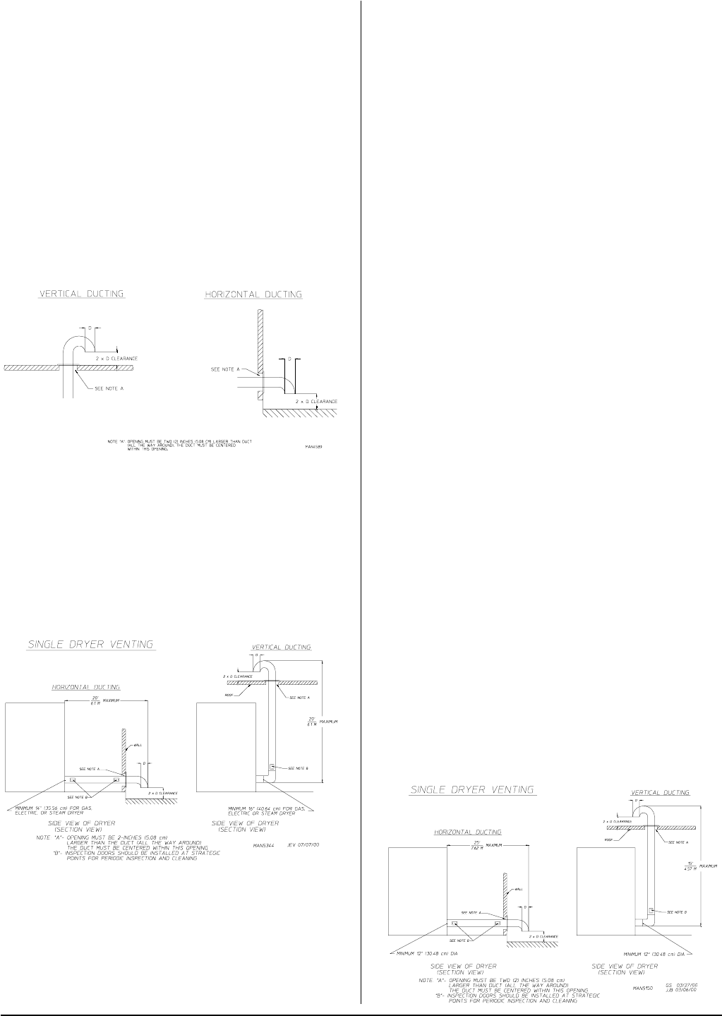
Exhaust back pressure measured by a manometer at each
dryer exhaust duct area must be no less than 0 and must
not exceed 0.3 in wc (0.74 mb) for the ML-130 model.
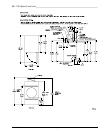
ML-130DR Single Dryer Venting