


IMPORTANT
You must disconnect and lockout the electric
supply and the gas supply or the steam supply
before any covers or guards are removed from
the machine to allow access for cleaning,
adjusting, installation, or testing of any equipment
per OSHA (Occupational Safety and Health
Administration) standards.
Please observe all safety precautions displayed
on the equipment and/or specified in the
installation manual included with the dryer.
CAUTION
Dryer(s) should never be left unattended while in
operation.
“Caution: Label all wires prior to disconnection
when servicing controls. Wiring errors can cause
improper operation.”
«Attention: Lor des opérations d’entretien des
commandes étiqueter tous fils avant de les
déconnecter. Toute erreur de câblage peut étre
une source de danger et de panne.»
WARNING
Children should not be allowed to play on or near
the dryer(s). Children should be supervised if near
dryer(s) in operation.
Under no circumstances should the dryer door
switch(es), lint door/drawer switch(es), or heat
safety circuit(s) ever be disabled.
The dryer must never be operated with any of the
back guards, outer tops, or service panels
removed. Personal injury or fire could result.
The dryer must never be operated without the lint
filter/screen in place, even if an external lint
collection system is used.
FOR YOUR SAFETY
Do not dry mop heads in the dryer. Do not use
dryer in the presence of dry cleaning fumes.
The dryers must not be installed or stored in
an area where it will be exposed to water
and/or weather.
The wiring diagram for the dryer is located in
the front electrical control box area.
Table of Contents
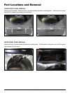
Part Locations and Removal ................ 4
Lower Front Panel Removal ......................................... 4
Upper Front Panel Removal ......................................... 4
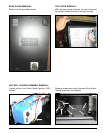
Back Guard Removal ................................................... 5
Top Cover Removal ....................................................... 5
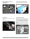
Lint Box / Blower Assembly Removal........................... 5
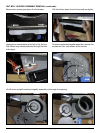
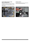
Gas Valve Removal ...................................................... 7
Oven Removal .............................................................. 7
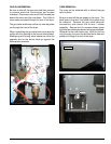
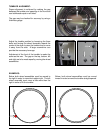
Tumbler Support Wheel Assembly Replacement ......... 8
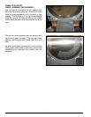
Tumbler Alignment ....................................................... 9
Electrical Component Locations........ 10
Electrical Panel ......................................................... 10
Oven Contactor .......................................................... 10
Door Switch ............................................................... 10
Fire Suppression System Items and Sail Switch ........ 11
Direct Spark Ignition (DSI) Module .............................. 11
Flame-Probe ............................................................... 11
Flame-Probe Positioning .............................................11
Exhaust Probe, Exhaust Hi-Limit, and Lint Drawer
Switch........................................................................ 12
Rotation Switch ......................................................... 12
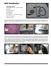
Belt Installation ................................... 13
Placing the Belt Back on the Motor Sheave............... 15