


8
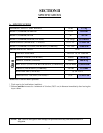
SECTION III
INSTALLATION PROCEDURES
Installation should be performed by competent technicians in accordance with local and state codes. In the
absence of these codes, the installation must conform to applicable American National Standards: ANSI Z223.1-
LATEST EDITION (National Fuel Gas Code) or ANSI/NFPA NO. 70-LATEST EDITION (National Electrical
Code) or in Canada, the installation must conform to applicable Canadian Standards: CAN/CGA-B149.1-M91
(Natural Gas) or CAN/CGA-B149.2-M91 (Liquid Propane [L.P.] Gas) or LATEST EDITION (for General
Installation and Gas Plumbing) or Canadian Electrical Codes Parts 1 & 2 CSA C22.1-1990 or LATEST EDITION
(for Electrical Connections).
A. UNPACKING/SETTING UP
Remove protective shipping material (i.e., plastic wrap, and/or optional shipping box) from dryer.
NOTE: The access keys for the service doors are included in the information packet shipped in the
basket (tumbler). These keys should be removed and put in a safe place, yet made
accessible because some will be needed throughout various phases in the installation of the
dryer.
Dryers are shipped with a coin box and coin box faceplate ONLY. The coin box lock is not included and
must be purchased elsewhere or the lock can be ordered as a parts order from the ADC Parts Department at
(508) 678-9000.
The dryer can be moved to its final location while still attached to the skid or with the skid removed. To unskid
the dryer, locate and remove the four (4) bolts securing the base of the dryer to the wooden skid. Two (2) are
at the rear of the base and two (2) are located in the front. Once the bolts are removed, slide the dryer off of the
skid.
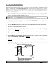
With the skid removed to make it easier to slide the dryer into its final position, slightly lower ALL the leveling
legs so that the dryer will slide on the legs instead of the base frame. The dryer is equipped with four (4) leveling
legs, one (1) at each corner of the dryer base. The hex head adjustment bolts for the two (2) front leveling legs
are located directly behind the lower access door and the rear two (2) adjustments are directly behind the lower
rear back guard panel.
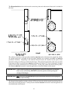
1. Leveling The Dryer
To increase the bearing life, improve efficiency, and provide for better automatic closure of the main door,
the basket (tumbler) should be tilted slightly to the rear. Four (4) leveling legs are provided for this
purpose and are shipped inside of the top basket (tumbler) and must be installed at the time of installation.
A leveling leg must be screwed into the bottom of the dryer base at each corner area, where the bolts used
to secure the dryer to the wooded skid were removed.