


SECTION V
SERVICING ....................................................................................................... 16
Introduction.................................................................................................................................... 16
A. Computer Controls .................................................................................................................... 17
B. Ignition Controls ........................................................................................................................ 18
C. Thermostats .............................................................................................................................. 22
D. Sail Switch Assembly (Gas Models Only) .................................................................................. 23
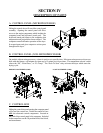
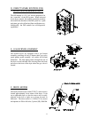
E. Front Panel and Main Door Assemblies ..................................................................................... 24
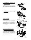
F. Pulleys ...................................................................................................................................... 27
G. Basket (Tumbler) Assembly ....................................................................................................... 29
H. Bearings (Refer To The Illustrations In Section F “Pulleys”) ........................................................ 31
I. V-Belts (Refer To The Illustrations In Section F “Pulleys”) .......................................................... 33
J. Motors and Impellors ................................................................................................................ 34
K. To Replace Lint Drawer Switch ................................................................................................. 36
SECTION VI
TROUBLESHOOTING ..................................................................................... 37
SECTION VII
ELECTRICAL TROUBLESHOOTING ........................................................... 41
A. Phase 5 OPL System Diagnostics .............................................................................................. 41
B. L.E.D. Display Indicators .......................................................................................................... 42
C. L.E.D. Display/Codes ............................................................................................................... 44
D. Computer Logic and Wiring Diagram ......................................................................................... 48
SECTION VIII
TECHNICAL INFORMATION......................................................................... 53
A. Motor Data Label (High and Low Voltage) ................................................................................ 53
B. Data Label ................................................................................................................................ 54
C. Using A Manometer................................................................................................................... 55
D. Tool List.................................................................................................................................... 56