


14 American Dryer Corp. 113215-5
7/11/08
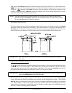
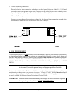
3. Grounding
A ground (earth) connection must be provided and installed in accordance with state and local codes. In
the absence of these codes, grounding must conform to applicable requirements of the National Electrical
Code ANSI/NFPA NO. 70-LATEST EDITION, or in Canada, the installation must conform to applicable
Canada Standards: Canadian Electrical Codes Parts 1 & 2 CSA C22.1-1990 or LATEST EDITION. The
ground connection may be to a proven earth ground at the location service panel.
For added personal safety, when possible, it is suggested that a separate ground wire (sized per local codes)
be connected from the ground connection of the dryer to a grounded cold water pipe. DO NOT ground to
a gas pipe or hot water pipe. The grounded cold water pipe must have metal-to-metal connection ALL
the way to the electrical ground. If there are any nonmetallic interruptions, such as, a meter, pump, plastic,
rubber, or other insulating connectors, they must be jumped out with no. 4 copper wire and securely
clamped to bare metal at both ends.
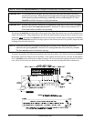
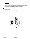
IMPORTANT: For personal safety and proper operation, the dryer must be grounded.
Provisions are made for ground connection in each dryer at the electrical service connection area.
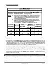
2.
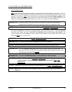
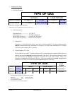
Electrical Service Specifications
GAS MODELS
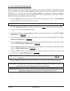
ELECTRICAL SERVICE SPECIFICATIONS (PER POCKET)
IMPORTANT:
NOTES
: A.
B.
C.
208 VAC AND 240 VAC ARE
NOT THE SAME. When ordering,
specify exact voltage.
When fuses are used they must be dual element, time delay, current
limiting, class RK1 or RK5 ONLY. Calculate/determine correct fuse
value, by applying either local and/or National Electrical Codes to
listed appliance amp draw data.
Circuit breakers are thermal-magnetic (industrial) motor curve type
ONLY. For others, calculate/verify correct breaker size according to
appliance amp draw rating and type of breaker used.
Circuit breakers for 3-phase (3ø) dryers must be 3-pole type.
SERVICE
VOLTAGE
PHASE
WIRE
SERVICE
APPROX.
AMP DRAW
CIRCUIT
BREAKER
60 Hz 50 Hz
120 1ø 2 8.7 – 15
208 1ø 2 5.2 – 15
240 1ø 2 4.8 4.7 15
208 3ø 3 3.0 – 15
240 3ø 3 3.2 – 15