


© Copyright, Alliance Laundry Systems LLC – DO NOT COPY or TRANSMIT F232084
6
Introduction
Model Identification
Information in this manual is applicable to these
models:
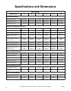
This manual is designed as a guide to the installation
of the Pocket Hardmount washer-extractor equipped
with the AC inverter drive.
NOTE: All information, illustrations, and
specifications contained in this manual are based
on the latest product information available at the
time of printing. We reserve the right to make
changes at any time without notice.
Delivery Inspection
Upon delivery, visually inspect crate, protective cover,
and unit for any visible shipping damage. If the crate,
protective cover, or unit is damaged or signs of
possible damage are evident, have the carrier note the
condition on the shipping papers before the shipping
receipt is signed, or advise the carrier of the condition
as soon as it is discovered.
Remove the crate and protective cover as soon after
delivery as possible. If any damage is discovered upon
removal of the crate and/or protective cover, advise the
carrier and file a written claim immediately.
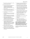
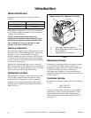
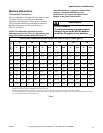
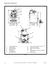
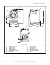
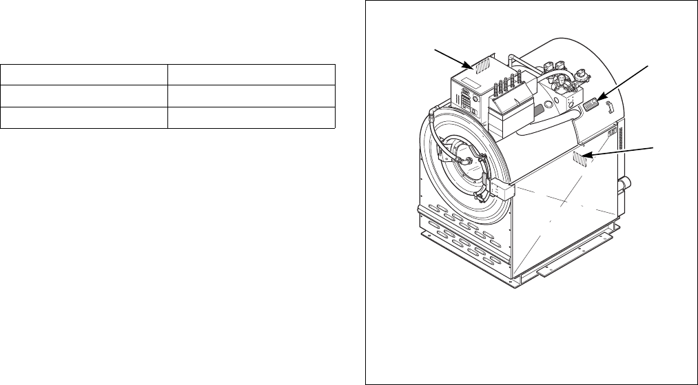
Nameplate Location
The nameplate is located on cagewrap, on side of AC
Inverter Drive Compartment and on Electric Heat
Contractor Box (if equipped). Always provide the
machine’s serial number and model number when
ordering parts or when seeking technical assistance.
Refer to Figure 1.
Figure 1
Replacement Parts
If literature or replacement parts are required, contact
the source from which the washer-extractor was
purchased or contact Alliance Laundry Systems LLC
at (920) 748-3950 for the name of the nearest
authorized parts distributor. A parts manual may be
ordered by returning the reply card provided with each
washer-extractor.
Customer Service
For technical assistance, contact your local distributor
or call:
(920) 748-3121
Ripon, Wisconsin
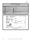
A record of each washer-extractor is on file with the
manufacturer. Always provide the machine’s serial
number and model number when ordering parts or
when seeking technical assistance. Refer to Figure 1
and Figure 2.
UW35PV UW60PV
UW80PV UW100PV
UW125PV UW150PV
PHM618N
1 Near Supply Valves on Cagewrap
2 Below Inverter Exhaust Fan on Electric Heat
Box (if equipped)
3 Side of AC Drive Compartment-
P
U
S
H
1
2
3
MODEL EXAMPLE OF NAMEPLATE LOCATION