


© Copyright, Alliance Laundry Systems LLC – DO NOT COPY or TRANSMIT
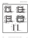
Specifications and Dimensions
F232084
26
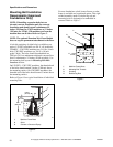
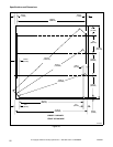
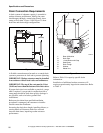
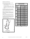
Drain Connection Requirements
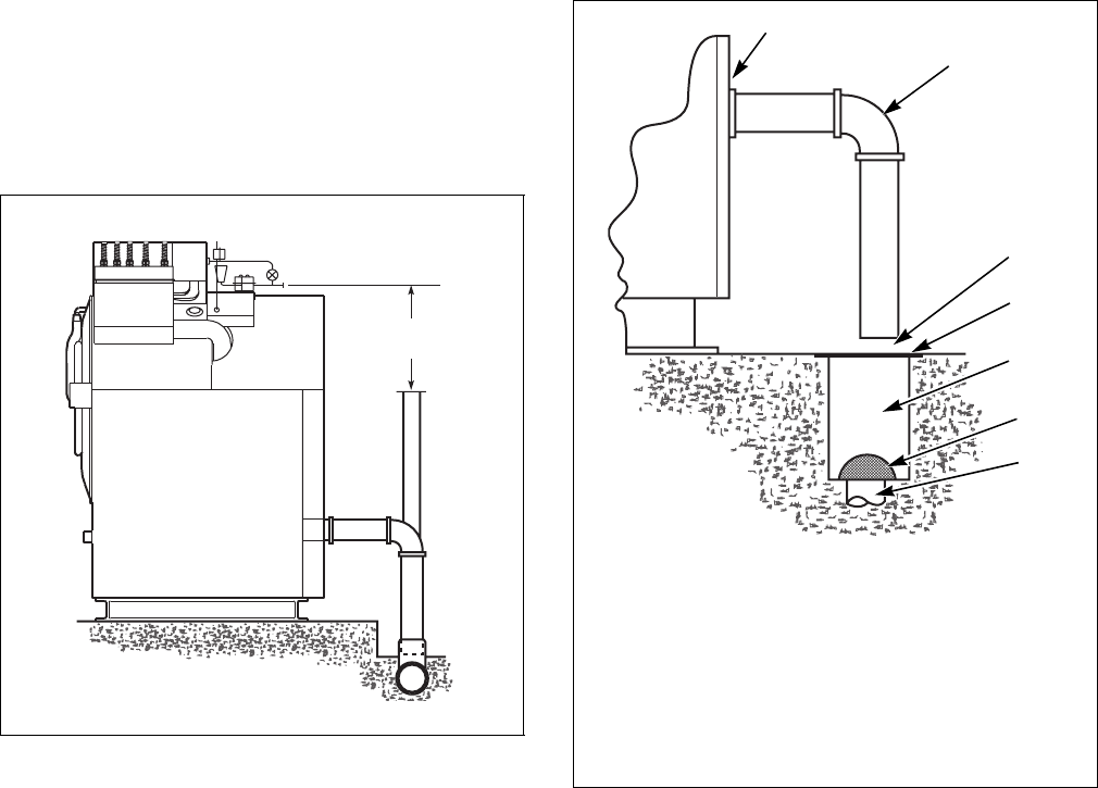
A drain system of adequate capacity is essential to
washer-extractor performance. Ideally, the water
should empty through a vented pipe directly into a
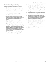
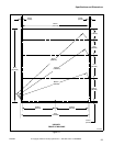
sump or floor drain. Figure 14 and Figure 15 show
drain line and drain trough configurations.
Figure 14
A flexible connection must be made to a vented drain
system to prevent an air lock and to prevent siphoning.
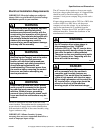
IMPORTANT: Washer-extractor must be installed
in accordance with all local codes and ordinances.
IMPORTANT: The top of the vent must be 1 foot
(30.48 cm) lower than the bottom of the inlet valves.
If proper drain size is not available or practical, a surge
tank is required. A surge tank in conjunction with a
sump pump should be used when gravity drainage is
not possible, such as in below-ground-level
installations.
Before any deviation from specified installation
procedures is attempted, the customer or installer
should contact the distributor.
Increasing the drain hose length, installing elbows, or
causing bends will decrease drain flow rate and
increase drain times, impairing washer-extractor
performance.
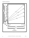
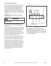
Figure 15
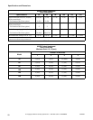
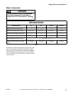
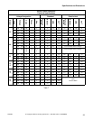
Refer to Table 3 for capacity-specific drain
information.
Installation of additional washer-extractors will
require proportionately larger drain connections. Refer
to Table 4.
PHM620N
1 ft.
(30.48 cm)
PHM621N
1 Rear of Machine
2 Drain Pipe
3 1 Inch Minimum Air Gap
4 Steel Grate
5 Drain Trough
6 Strainer
7 Waste Line
4
1
2
5
6
7
3