


© Copyright, Alliance Laundry Systems LLC – DO NOT COPY or TRANSMIT
Installation Instructions
M412060
18
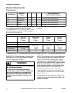
Gas Requirements (Gas Drying Tumblers)
Before connecting the gas piping to the tumbler, make
certain that gas service is the same as that specified on
the serial plate.
IMPORTANT: Any product revisions or
conversions must be made by the Manufacturer’s
Authorized Dealers, Distributors or local service
personnel.
IMPORTANT: The installation must comply with
local codes or, in the absence of local codes:
- with the latest edition of the “National Fuel Gas
Code”, ANSI Z223.1 in the U.S.A.
- with CAN1-B149.1 or CAN1-B149.2 in Canada
- and Australian Gas Association/Australian L.P.
Gas Association requirements in Australia
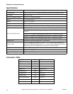
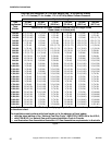
The size of gas service pipe is dependent upon many
variables (lengths, tees, etc.). Specific pipe size
information should be obtained from the gas supplier.
Refer to table in Figure 7 for general pipe size.
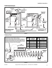
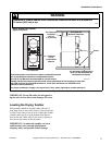
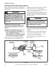
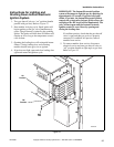
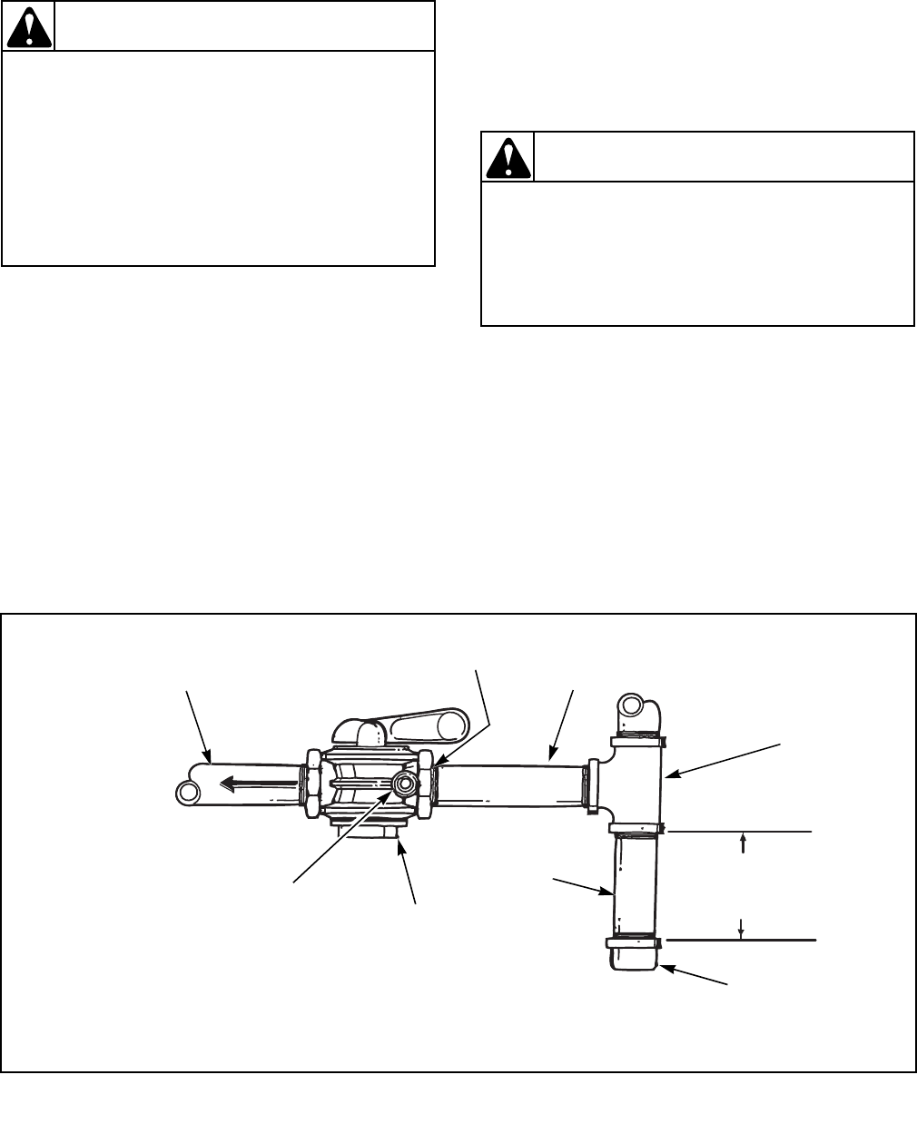
A dirt and water vapor pipe trap must be furnished and
installed by customer. Refer to Figure 6.
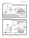
It is important that equal pressure be maintained at all
tumbler gas connections. This can best be done by
installing a one inch (2.54 cm) pipe gas loop as shown
in Figures 8 and 9.
Before connecting the gas piping to the tumbler, make
certain gas service is the same as that specified on the
serial plate.
NATURAL GAS service must be supplied at 6-1/2 ±
1-1/2 inch water column pressure (1.62 ± .37 kPa).
L.P. GAS service must be supplied at 11 ±.3 inch
water column pressure (2.74 ±.07 kPa).
Pressure checks can be made at the shut-off valve.
Refer to Figure 6.
To reduce the risk of fire or explosion, DO
NOT CONNECT THE GAS LINE TO THE
TUMBLER IF THE GAS SERVICE IS NOT
THE SAME AS THAT SPECIFIED ON THE
TUMBLER SERIAL PLATE! It will first be
necessary to convert the gas burner orifice
and gas valve. Appropriate conversion kits
are available.
W060
WARNING
To reduce the risk of fire or explosion, if the
tumbler is to be connected to Liquefied
Petroleum (L.P.) gas, a floor level vent to
the outdoors must be provided in the room
where the tumbler is installed.
W098
WARNING
Figure 6
TMB2158N
1/8 in (.32 cm) N.P.T. plugged
tapping accessible for
pressure testing. Gauge
connection located upstream
from dryer main manual
shut-off
Gas Line to
Dryer Controls
1/2 in Reduced
to 3/8 in
1/2 in Gas
Supply Piping
System
Gas “T”
Fitting
6 Inches (15.2 cm)
Minimum Gas
Pipe
Gas
Pipe Cap
Shut-Off
Valve
Dirt and
Water Vapor
Trap