


F232073 13
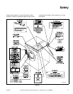
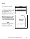
Safety
© Copyright, Alliance Laundry Systems LLC – DO NOT COPY or TRANSMIT
Theory of Operation
The design of the machine emphasizes performance
reliability and long service life. The cylinder, shell,
and main body panels are fabricated of stainless
steel.
The cylinder on 50-pound capacity machines and
smaller is supported with two sealed bearings
mounted in a machined cast iron trunnion bolted to
a heavy gamma frame.
On 80-pound capacity machines, the cylinder and
shaft assembly is supported by two flange roller
bearing assemblies. The bearing housings are bolted
to the frame.
The 2-speed machines use one dual-speed motor to
drive the cylinder via a V-belt drive in wash speed
and extract speed.
The 3-speed 18-pound capacity models use one
triple-speed motor, while all other 3-speed models
use one single-speed and one dual-speed motor to
drive the cylinder at wash speed, medium extract
speed, and high extract speed.
A door-lock system prevents opening of the
stainless steel door when water is in the machine. It
also prevents operation of the machine when the
door is open.
An electrically operated drain valve is used to retain
the water and wash solution in the machine during
the wash and rinse steps. The drain valve closes
when power is applied and opens when power is
removed, allowing the machine to drain in the event
of a power failure.
The cylinder is designed with lifters or ribs that lift
the garments from the wash solution when the
cylinder rotates at slow speed and allow the
garments to tumble back into the solution. The
cylinder is perforated, allowing the water to pass
through and drain from within during the wash
process and extract.
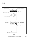
Electrical controls for the machine are housed in a
separate enclosure located underneath the top cover
of the machine.
The operator can select from among 30 cycles, 12
of which are preprogrammed at the factory. A
special permanent test cycle can be selected to
verify proper operation of the machine.
The polypropylene supply dispenser is located
under a flexible cover on the left side of the
machine, viewed from the front. The compartments
are numbered 1 – 3, starting from the left side of the
machine. A nozzle flushes dry supplies from the
compartment with water at the appropriate time in
the cycle.
Liquid supplies can be injected directly into the
dispenser compartments by a customer-supplied
external chemical supply system. Four hose barbs
on the rear of the machine facilitate connection to
an external chemical supply system. A terminal
strip in the input power junction box provides
control signals.