


© Copyright, Alliance Laundry Systems LLC – DO NOT COPY or TRANSMIT
Introduction
9
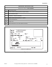
F232157
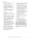
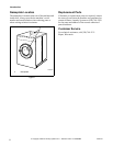
Electronic Control Unit
The “B” electronic control is composed of the
electronic control unit and the control fuse board with
wiring harness. Only an authorized person should look
inside the control compartment. First TURN OFF
POWER, open lid and remove any cover present.
Make sure door lock circuit has fully discharged. The
door unlock capacitor can retain high electrical charge,
even when the machine’s electrical inputs are
disconnected, until it has discharged. Some machines
are equipped with an orange or red indicator light
facing upward in the control compartment. If this is
on, wait until light goes off (indicating when high
voltage in the door lock circuit has discharged). The
components are described below.
This portion of the control contains the “intelligence” –
the micro-controller and the miscellaneous components
on the printed circuit (PC) board. The board has a
metal cover, which MUST be in place at all times
during machine operation. Operation of the machine
without this cover installed will void the warranty.
The control unit monitors and responds to input, gives
information about the status of the washer and
monitors and responds to inputs from the user
interface (keypad). The control provides signals to the
control output unit, which in turn operates the
components that control the machine functions. This is
located behind the machine control panel.
Control Output Fuse Board
This portion of the control contains the power supply
for the control unit, and also the switching devices
which power the components in the machine, all of
which are on the output PC board. The switching
devices are controlled by the control unit, and are solid
state.
Summary of Control Outputs and
Inputs
Outputs
General outputs provide signals to operate the
following components.
1. Hot Fill Valve (HF)
2. Cold Fill Valve (CF)
3. Drain Valve (normally open) (DR)
4. Door Lock Solenoid Coil (DL)
5. Door Unlock Solenoid Coil (DU)
6. Supply 1 (detergent) (S1)
7. Supply 2 (bleach) (S2)
8. Supply 3 (sour/softener) (S3)
9. Optional 3rd (Extra) Fill Inlet (governed by the
configuration settings) (S4)
10. Optional Heat (HT)
11. *Prep for Card Reader or Central Pay (“machine
available signal”)
For standard models, the components for outputs
shown as “optional” will not be populated on the
output printed circuit board.
AC outputs are solid state outputs that operate either
120 Volt AC or 220 Volt AC (nominal voltage)
components, depending on the control voltage
configuration. Outputs are fused appropriately.
Inputs
1. Low Water Level
2. Medium Water Level
3. High Water Level
4. Door
5. Coin 1 Signal
6. Coin 2 Signal
7. *Prep for Card Reader or Central Pay (“start
pulse”)
* This allows machine to interface with the card reader or the
central pay system. “Start Pulse” originates from the reader/
central pay system, and this satisfies the programmed vend.
B control provides “Machine Available” signal to reader/
central pay when it is ready to accept payment. Refer to
Machine Electrical Schematic.
Control Voltage
The control power supply can be configured to operate
on 110 Volt AC nominal RMS input voltage
50/60 Hertz, OR 220 Volt AC nominal RMS input
voltage 50/60 Hertz.
Harnessing
Wiring harnesses are modular – harnesses common to
various configurations are similar, while those specific
to a certain configuration can be added. There are
harnesses for inputs to the control unit, for outputs
from the control power/output unit to the machine
components, and for the main incoming power to the
control power/output unit.