


Installation
40
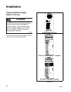
F232058
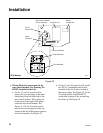
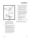
Note: Ensure cables are routed safely and
away from potential hazards. Use wire ties,
included with the kit, to secure cabling.
Provide some slack for repositioning of the
canister/filter/pump assembly after electrical
connections are made.
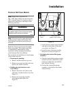
d. One the 35- and 50-pound models,
route the 2-conductor and 4-conductor
cable through the two PG 13.5 strain
reliefs installed in step b. See Figure 23.
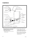
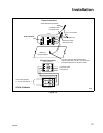
On the 85-pound model, route both the
2-conductor cable and the 4-conductor
cable through the PG 21 strain relief as
shown in Figure 24.
Note: Ensure strain reliefs are tightened
securely around the cable.
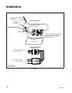
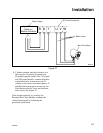
e. Connect red wire in the 2-conductor
cable from the canister/filter/pump
assembly to terminal A2 of the pump
contactor. See Figure 23.
f. Extend 2-conductor cable #223, which
is capped in the rear control module.
Connect red wire of #223 to the black
wire of the 2-conductor cable from the
canister/filter/pump assembly.
g. Connect the black wire of the #223
cable to terminal A1 of the pump
contactor.
h. Connect L1, L2, and L3 from the circuit
breaker to the input side of the mains
contactor, using the 18GA gray wire,
included in the kit.
i. Connect the 4-conductor cable wires to
the pump contactor terminals as
follows: wire No. 1 to terminal T1, wire
No. 2 to T2, and wire No. 3 to T3. Wire
No. 4 (green-yellow) must be
connected to the chassis ground.
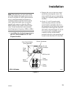
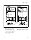
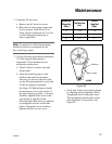
Note: If pump motor rotation is incorrect
during the control function test, swap any two
wires at terminals T1, T2, or T3 of pump
contactor. See Figure 26 for correct motor
rotation direction.
7. Verifying electrical connections:
a. Secure any loose or dangling wires,
using the wire ties.
b. Verify that all connections are secure
and routed properly.
8. Reassembling machine panels:
a. Reassemble rear panel and right front
panel.
b. Reinstall rear control module cover.
9. Install water recirculation piping:
a. Remove the cap on the recirculation
inlet on top of the shell. See
Figure 20.
b. Attach the 1 1/2-inch black hose
connector (no clamp grooves), included
in the kit, between the shell
recirculation inlet and the adapter plate.
c. Attach upper recirculation pipe to the
hose connector at the recirculation
adapter plate on the rear of the washer-
extractor. See Figure 26.