


35
Installation
F232058
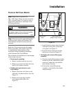
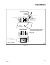
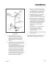
Note: The cable has a red wire and a black
wire. The machine drain valve wires are red
for ACN and black for ACH. Splice both red
wires in one blue terminal and connect to
common terminal of washer-extractor drain
valve. Splice both black wires in one blue
terminal and connect to either the 50Hz or
60Hz terminal of the washer-extractor drain
valve. Verify that the drain valve terminals
match input power frequency (50Hz or 60Hz).
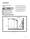
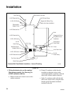
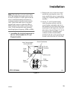
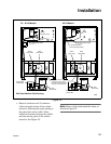
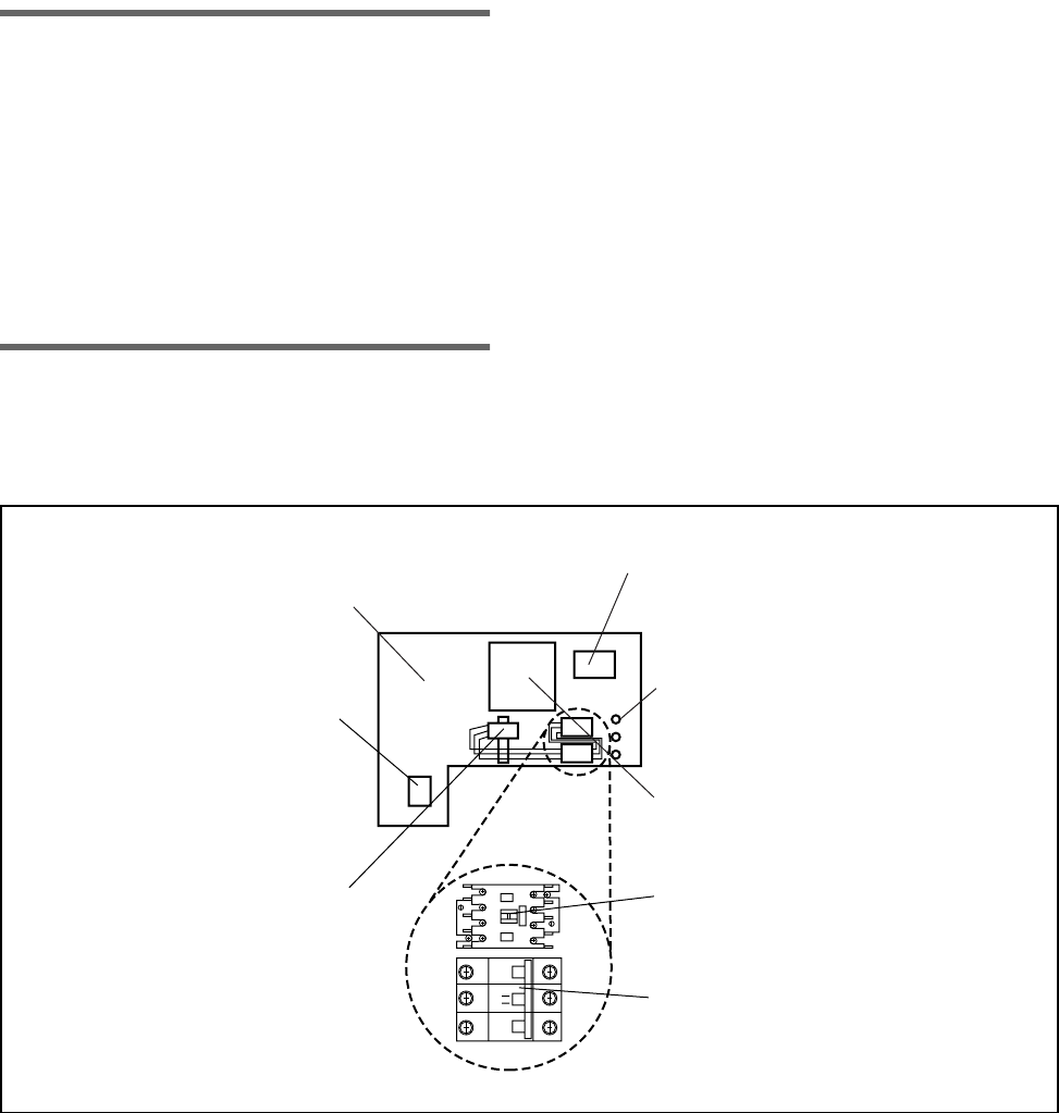
5. Assembling the electrical components in
the rear control module for 35- and
50-pound models:
a. Remove the cover on the rear control
module by removing the screws. On
newer models the cover is removed by
using a key originally shipped with the
machine.
b. On the 35- and 50-pound models,
attach the pump contactor and the
circuit breaker, included in the kit, to
the mounting rail just below the control
transformer on the right side of the AC
drive unit as shown in Figure 21. On the
85-pound models, attach the pump
contactor and the circuit breaker,
included in the kit, to the mounting rail
located to the left of the AC drive unit.
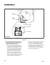
Figure 21
UF35 & 50 Models
R006I
OFF ON
L1 L2
A1
A2
NX1O1
L3 L4
T1 T2 T3 T4
Rear Control Module
(cover removed)
Control Transformer
Power
Input
Block
Mains
Contactor
PG 13.5
Connector
AC Drive Unit
Pump
Contactor
Circuit
Breaker