


31
Installation
F232058
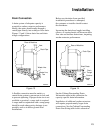
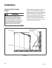
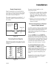
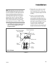
Supply Compartments
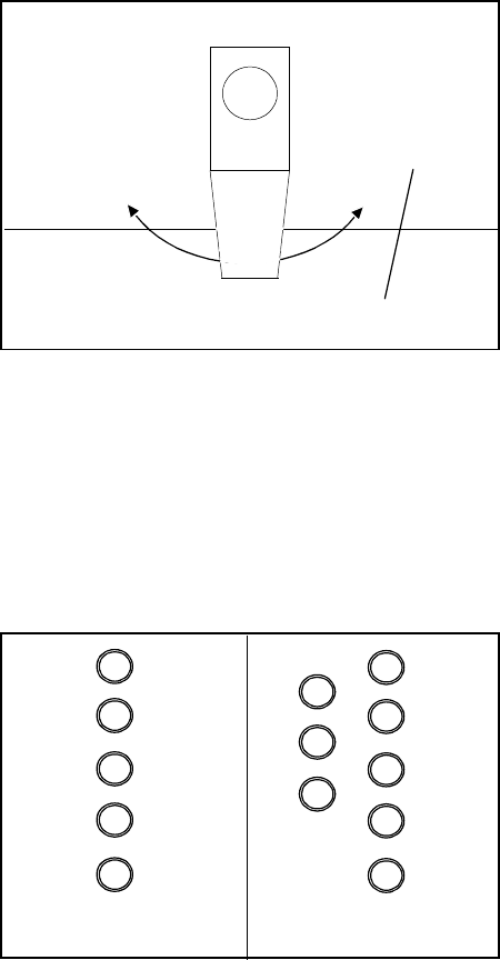
Supply compartments are located behind an
access door on the top left side of the machine
front. The door can be opened by turning the
door latch as shown in Figure 16.
The supply compartments are numbered 1 – 5,
from left to right as viewed from the front of
the machine.
Figure 16
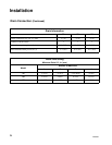
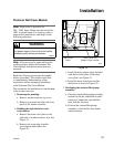
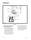
Connecting External Supplies
Hose barbs are located on the right rear of the
machine. Connections are numbered as shown
in Figure 17.
Figure 17
To connect external supplies, use the
following procedure:
1. Connect tubes to supply inlets by pushing
each tube over inlet lip. Tubes should fit
snugly onto supply inlets. When seated
completely, tube ends should contact rear
of machine.
2. Tightness of fit will dictate whether or not
hose clamps are necessary. No. 8 hose
clamps are suitable.
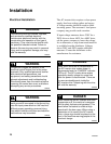
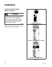
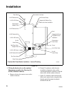
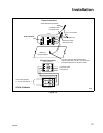
Electrical Connections for Chemical
Injection Supply Systems
A stainless steel box at the rear of the machine
houses a terminal strip which furnishes supply
output signals for the chemical injection
supply pumps. See Figure 18 for examples of
applicable decals.
Terminals SUPPLY 1 through SUPPLY 8
provide 100-120VAC fused at 500mA. These
terminals may be used to provide signals to the
chemical injection system but must not be used
to provide power to the pump. Do not attempt
to increase fuse rating as this may cause
damage to the washer-extractor’s circuitry.
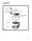
An external chemical injection system
requiring 200-240VAC can be powered
through LINE 1 and LINE 2 on the external
supply terminal strip on PVQ and PVT
models. Any chemical injection system used
with PVM, PVN, and PVP models must be
powered by a separate independent power
source.
Any injection system pump which requires
110VAC must be powered by a separate
external power source.
Supply Door
Turn latch either
direction to open
supply door.
1
2
3
4
5
1
2
3
4
5
6
7
8
5 supply models 8 supply models