2-20
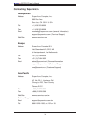
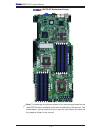
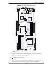
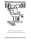
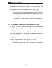
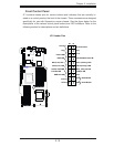
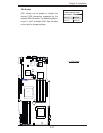
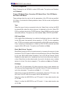
X8DTG-DF User's Manual
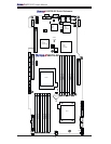
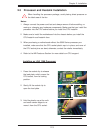
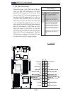
JPW2
JPW3
J11
+
LE4
SW1
JPW1
FAN4
FAN8
FAN7
FAN3
FAN1
4
1
FAN2
FAN6
FAN5
JLPC80
JPCIE3
JWD1
JPL1
JPG1
LE1
LE2
JBAT1
JL1
JNMI1
JSPK1
J_UID_OW
PHY
x4 in x16 Slot
SBX 2B
SBX 1B
PCI-E 2.0
SBX 2A
IPMB
T-SGPIO0
IPMI_LAN
USB2/3
SBX 1A
P2 DIMM1A
P1DIMM3A
P2 DIMM1B
P1 DIMM2B
P2 DIMM2A
P1 DIMM2A
P2 DIMM2B
P1 DIMM1B
P2 DIMM3A
P1 DIMM1A
P2 DIMM3B
CLEAR
VGA
COM1
LAN2
LAN1
USB0/1
CMOS
I-SATA1
JPI2C (PWR I2C)
CPU1
CPU2
BIOS
T-SGPIO1
I-SATA2
I-SATA3
I-SATA4I-SATA5
I-SATA6
Intel
ICH10R
(South Bridge)
Intel
5520
IOH-36D
Intel
82576
LAN CTRL
Winbond
450R
BMC
P1 DIMM3B
Front Panel CTRL
Battery
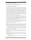
X8DTG-DF
J12
JPCIE1
JPCIE2
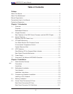
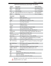
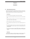
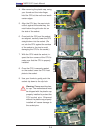
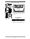
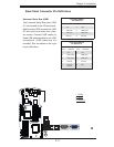
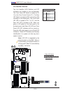
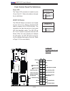
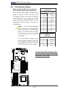
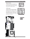
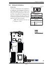
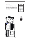
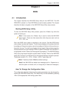
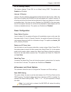
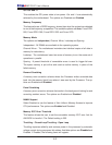
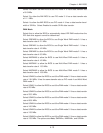
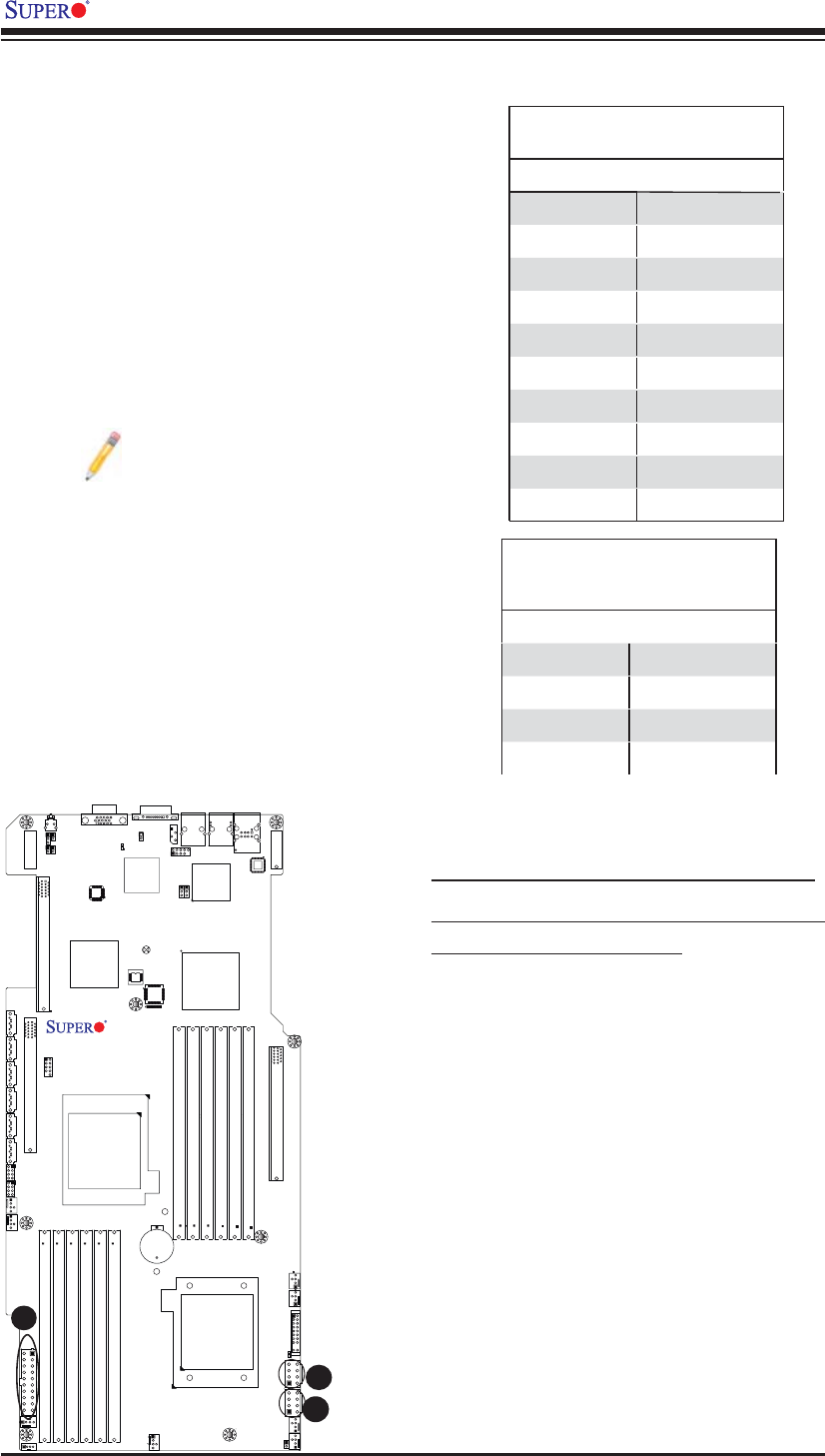
2-6 Connecting Cables
A
C
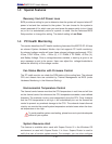
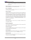
20-pin Proprietary Main Power and 8-pin
PCI-E Graphic Card Power Connectors
There are one 20-pin SMC Proprietary main
power connector (JPW1) and two 8-pin
PCI-Express graphic card power connectors
(JPW2/JPW3) on the motherboard. These
power connectors meet the SSI EPS 12V
specifi cation. See the tables on the right for
pin defi nitions.
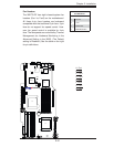
Notes: 1. For the these proprietary
PWR Connectors to work properly,
please customize your PWR cables
based on the SMC PWR Connector
Pin-Out Defi nitions listed in the tables
on the right.
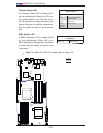
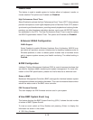
2. For the PCI-Exp. Graphic cards
to work properly, please connect the
PCI-E graphic card power connectors
(JPW2/JPW3) to the power supply.
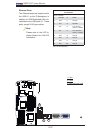
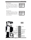
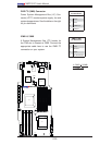
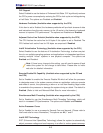
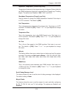
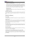
20-pin Main Power Connector
Pin Defi nitions
Pin# Defi nition Pin # Defi nition
11 PS On 1 Ground
12 5VSB 2 Ground
13 Ground 3 Ground
14 Ground 4 Ground
15 Ground 5 Ground
16 NC2 6 NC1
17 12V 7 12V
18 12V 8 12V
19 12V 9 12V
20 12V 10 12V
A. 20-pin Main PWR connector (JPW1)
B/C. 8-pin PCI-E Graphic Card PWR
connectors (JPW2/JPW3)
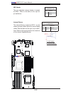
B
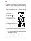
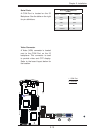
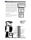
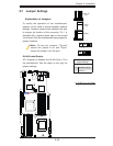
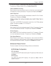
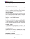
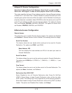
8-pin PCI-E Graphic Card Power
Connector
Pin Defi nitions
Pin# Defi nition Pin # Defi nition
1 12V 5 Ground
2 12V 6 Ground
3 12V 7 Ground
4 Ground 8 Ground