9
Part Names and Functions
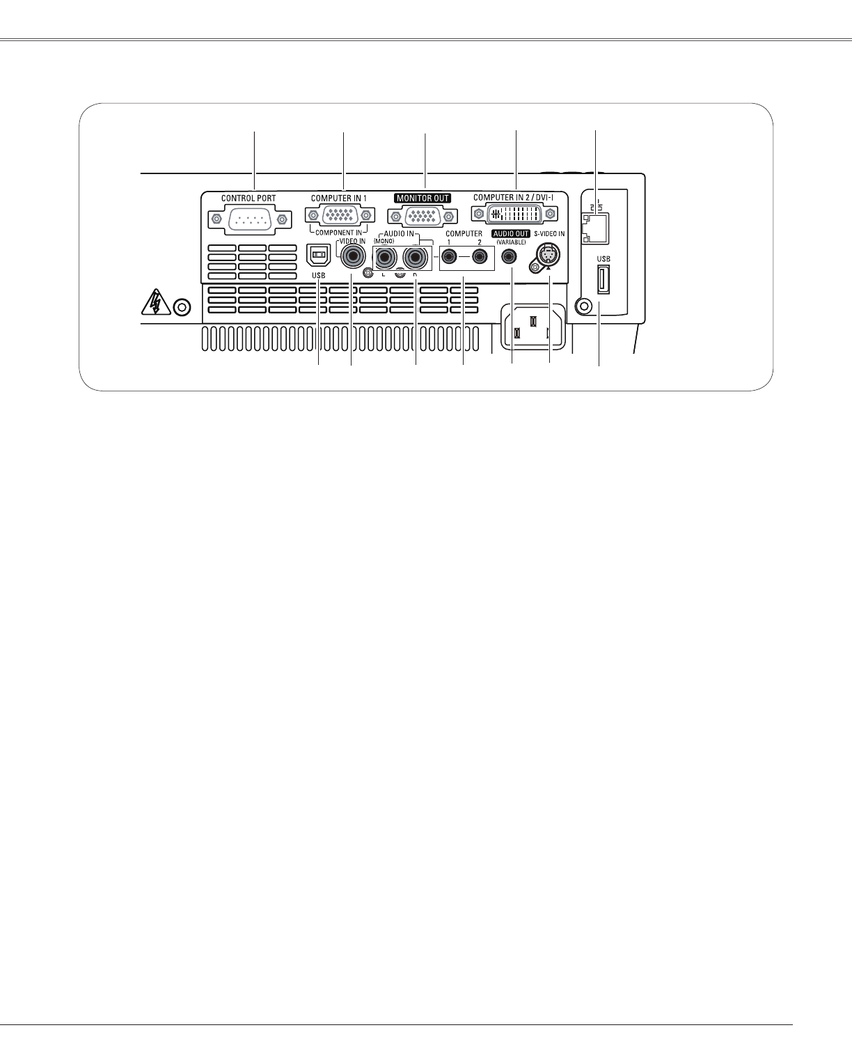
Rear Terminal
⑦S-VIDEO IN
ConnecttheS-VIDEOoutputsignalfromvideo
equipmenttothisjack(p.17).
⑩ AUDIO IN
Connecttheaudiooutputsignalfromvideo
equipmentconnectedto
⑦or⑪tothisjack.
Foramonoaudiosignal(asingleaudiojack),
connectittotheL(MONO)jack(p.17).
⑨ COMPUTER 1 / COMPUTER 2 AUDIO IN
Connecttheaudiooutput(stereo)froma
computerorvideoequipmentconnectedto
②
or④tothisjack.(pp16,18)
⑪ VIDEO IN
Connectthecompositevideooutputsignalto
thisjack(p.17).
② COMPUTER IN 1 / COMPONENT IN
Connectoutputsignalfromacomputer,RGBscart
21-pinvideooutputorcomponentvideooutputto
thisterminal(pp.16,18).
⑧ AUDIO OUT (VARIABLE)
Connectanexternalaudioamplifiertothisjack
(pp.16-18).
ThisterminaloutputssoundfromAUDIOIN
terminal(⑨or⑩).
③ MONITOR OUT
Thisterminalcanbeusedtooutputtheincoming
analogRGBsignalfromCOMPUTERIN2/DVI-I
terminalorCOMPUTERIN1/COMPONENTIN
terminaltotheothermonitor(p.16).
⑤ LAN Connection Terminal
ConnecttheLANcable(refertotheowner’smanual
“NetworkSet-upandOperation”).
⑫USB Connector (Series B)
Inordertooperatethecomputerwiththeremote
controlandusethePAGE
▲▼buttonsonthe
remotecontrolduringapresentation,connectthe
USBportofthecomputertotheUSBterminalwith
aUSBcable(notsupplied)(p.16).
⑥ USB Connector (Series A)
ConnecttheUSBcable(refertotheowner’smanual
“NetworkSet-upandOperation”).
② ③① ④ ⑤
⑥⑩ ⑦⑨
①CONTROL PORT
Whentheprojectoriscontrolledbyacomputer,
connecttothisjackwithserialcontrolcable.
④ COMPUTER IN 2 / DVI-I
Connectcomputeroutput(Digital/AnalogDVI-Itype)
tothisterminal(p.16).
⑧⑪⑫


