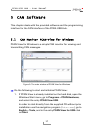
PCAN-USB Hub – User Manual
11
Tip: You can connect a can bus with a different transmission
standard via a bus converter. PEAK-System offers different bus
converter modules (e.g. PCAN-TJA1054 for a Low-speed CAN
bus according to ISO 11898-3).
3.3.1 Supplying External Devices via the CAN
C
onnector
By setting solder bridges on the PCB of the PCAN-USB Hub (casing
opened) a 5-Volt supply can be routed to pin 1 and the external
voltage supply, if available, can be routed to pin 9 of the D-Sub CAN
connector.
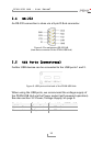
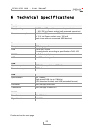
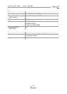
CAN D-Sub pin Voltage Max. current delivery
1 +5 V 100 mA
9 external supply voltage
(9 - 36 V)
2 A
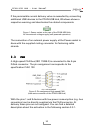
If the solder bridge for pin 9 is set, the state of this pin can be
switched by software (on/off). At delivery pin 9 is on referred to the
software part. On request we’ll provide you with additional informa-
tion and a Windows program for switching (contact information:
se
e on page 2).
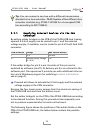
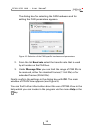
Proceed as follows to activate the 5-Volt supply and the external
voltage supply at the CAN connector:
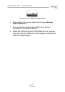
Remove the four lower corner screws from the aluminum casing of
the PCAN-USB Hub and then the bottom cover.
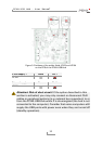
Set the solder bridge(s) on the PCB of the PCAN-USB Hub according
to the desired function. During this procedure take especially care
not to produce unwanted short circuits on the board.
The following figure shows the positions of the solder fields on the
PCB of the PCAN-USB Hub; the tables below contain the possible
settings.