Contents
PXI-1006 User Manual viii ni.com
Appendix A
Specifications
Appendix B
Pinouts
Appendix C
Technical Support Resources
Glossary
Index
Figures
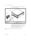
Figure 1-1. Installing Controller and PXI Modules................................................. 1-2
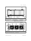
Figure 2-1. Front View of the PXI-1006 Chassis....................................................2-3
Figure 2-2. Rear View of the PXI-1006 Chassis.....................................................2-3
Figure 2-3. PXI Local Bus and Star Trigger Routing..............................................2-5
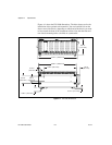
Figure A-1. PXI-1006 Dimensions........................................................................... A-6
Tables
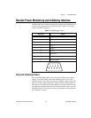
Table 2-1. DB-9 Connector Pinout ........................................................................2-7
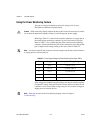
Table 2-2. Power Supply Voltages at Power Monitoring Connector (DB-9) ........ 2-8
Table 3-1. Troubleshooting.................................................................................... 3-1
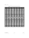
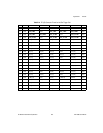
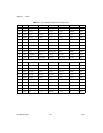
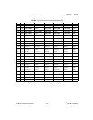
Table B-1. P1 (J1) Connector Pinout for the System Controller Slot..................... B-2
Table B-2. P2 (J2) Connector Pinout for the System Controller Slot..................... B-3
Table B-3. P1 (J1) Connector Pinout for the Star Trigger Slot............................... B-4
Table B-4. P2 (J2) Connector Pinout for the Star Trigger Slot............................... B-5
Table B-5. P1 (J1) Connector Pinout for the Peripheral Slot..................................B-6
Table B-6. P2 (J2) Connector Pinout for the Peripheral Slot..................................B-7