Chapter 2 PXI-1006 Features
© National Instruments Corporation 2-7 PXI-1006 User Manual
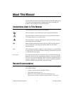
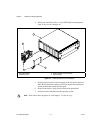
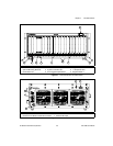
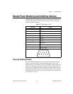
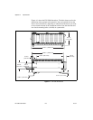
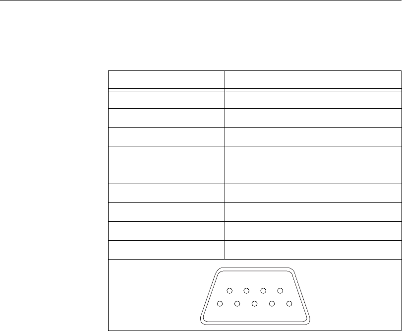
Remote Power Monitoring and Inhibiting Interface
The PXI-1006 chassissupports remote powermonitoring andinhibiting via
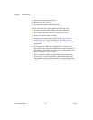
a 9-pin D-sub connector located on the rear panel. Table 2-1 shows the
pinout of the DB-9 connector.
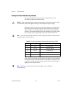
Using the Inhibiting Feature
You can use the Inhibit signal (active low) to turn off the power supply
outputs. To use this feature, connect the Inhibit pin (pin 5) to a Logic
Ground pin (pin 1 or 9). Make sure the front (standby) switch is in the ON
position. As long as the connection is made, the power supply inhibits its
DC outputs. DC output resumes when Inhibit is no longer connected. Note
that the power (standby) switch,located onthe front of thechassis, uses this
inhibiting feature. For remote reset, connect a momentary switch between
pin5andpin1(orpin9).
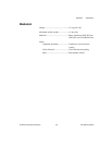
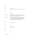
Table 2-1. DB-9 Connector Pinout
DB-9 Pin Signal
1 Logic Ground
2 +5 V
3 Reserved
4 +3.3 V
5 Inhibit*
6 +12 V
7 Reserved
8 –12 V
9 Logic Ground
6
7
89
1
2
3
4
5